background image

www.major-equipment.com

3

Free-wheeling parts Hazard

The heavier a revolving part is, the longer it will continue to rotate after power is shut off. This characteristic is called 

‘free-wheeling.’ Blades, and various other components, drive shafts etc., will continue to move after power is shut off - 

often for several minutes. Injuries occur when:

•  Operators shut off equipment, and attempt to clean or adjust a machine before components have completely stopped 

moving.

• 

Shear bolt protection device in PTO shaft shears & the mowing parts are still spinning but the primary PTO shaft is 

stationary.  Operator awareness is the key to safety around freewheeling parts. Never raise the machine while the 

blades are still rotating.

Thrown objects Hazard

Machines throw material as a natural part of doing their job. Foreign objects, such as stones, sticks and other debris, 

may be taken into this equipment and expelled at tremendous speed. These objects are contained by the sides of the 

machine and by the rear/front rollers / guards / chain guards / rubber skirts depending on model of your machine.

Ensure bystanders are clear from the machine & cannot be hit with debris expelled from the machine. Bystanders or 

animals in the path of thrown objects could be seriously injured. Never operate machine with decks raised from the 

ground as this makes the front/rear protection redundant.

Hydraulic Hazard 

(if applicable)

Hydraulic systems store considerable energy. Careless servicing, adjustment, or replacement of parts can result in 

serious injury. High pressure blasts of hydraulic oil can injure eyes or other body parts. The following precautions are 

crucial:

•  Make certain the hydraulic pump is turned off.

•  Lower attached equipment to the ground.

• 

Confirm that load pressure is off the system.

A pinhole leak in an hydraulic hose is a serious hazard. A leak may not be visible, and the only sign may be a few drops 

of fluid. Never inspect hydraulic hoses with your hands, because a fine jet of hydraulic fluid can pierce the skin. 

Slips, Trips and Falls Hazard

Slips and falls often result from:

1. Slippery footing on the ground 

2. Cluttered steps and work platforms.

The potential for slips and falls can be greatly reduced by using good judgement and practicing good housekeeping on 

and around equipment.

Noise Hazard

Please note that the machine is normally used outdoors and that the position of the operator is seated in the driving seat 

of the tractor. It is advisable to consult the prescriptions listed in tractor operator and maintenance manuals. 

The acoustic pressure at a distance of 2.6m from the centre of the machine and at a height of 2.0m, with the implement 

operating in a no load condition  can reach 90 dBA. In a loaded condition & a PTO rate of 540 (1000) RPM the value can 

reach 97dBA. Higher rate of PTO input will result in higher noise levels. Always wear hearing protection.

Operating Safely

This MAJOR machine is designed to operate at a PTO rate which is stated in the Product Specifications part of this 

booklet. Ensure tractor PTO output is set at a correct RPM rate. This MAJOR machine must only be used for purposes 

outlined in the Intended Use section of this booklet. All other use is strictly prohibited.

Users should become thoroughly familiar with the contents of this manual before using, servicing and 

mounting the implement to the tractor and all other pertinent operations. Never wear jewellery, loose clothing 

such as ties, scarves, belts, unbuttoned jackets or dungarees with open zips which could become caught up 

in moving parts.

Always wear approved garments complying with accident prevention provisions such as non-slip shoes, ear 

muffs, goggles and gauntlets. Wear a jacket with reflecting stickers if the implement is used near public 

highways.

Consult your retailer, the Labour Health Service or your nearest equivalent authority for the information about 

the current safety provisions and specific regulations with in order to ensure personal safety.

ALWAYS DISENGAGE PTO, SWITCH OFF THE TRACTOR ENGINE AND ENGAGE THE PARKING BRAKE 

BEFORE MAKING ADJUSTMENT TO THE MACHINE.

Summary of Contents for CONTOURA MJ76-360

Page 1: ...www major equipment com CONTOURA MJ76 360 Operator s Manual and Parts List WARNING Read this instruction manual thoroughly before using your machine and follow all safety precautions...

Page 2: ...us 29 NL 7700 AA Dedemsvaart Nederland Tel 31 0 6389 19585 Email euinfo major equipment com Web www major equipment com Disclaimer While every effort has been made in the production of this manual to...

Page 3: ...ct Identification Machine Serial Numbers 7 Product Specifications 7 EEC certificate of conformity for machines 8 Machine Safety Labels 9 Key to Main Parts 10 Blade Rotation 11 Blade system 12 Drive li...

Page 4: ...ist 32 MJ76 360 Right wing MJ76 360 WGGA01 33 MJ76 360 Right wing MJ76 360 WGGA01 Parts list 35 MJ76 360 Hydraulics 36 Hydraulic Ram spares 36 MJ76 Rollers 37 Roller End Parts List 37 MJ76 Blades 38 M...

Page 5: ...dealer or MAJOR The operator is solely responsible for the safe use and maintenance of the machine The machine must only be operated by a competent and skilled person Setting up and adjustment must on...

Page 6: ...fety The operator s manual also explains any potential safety hazards whenever necessary in special safety messages that are identified with the word CAUTION and the safety alert symbol Hazards associ...

Page 7: ...ds because a fine jet of hydraulic fluid can pierce the skin Slips Trips and Falls Hazard Slips and falls often result from 1 Slippery footing on the ground 2 Cluttered steps and work platforms The po...

Page 8: ...O input is specified in the Product Specifications section of this booklet Contact your nearest dealer or a specialised retail outlet if the PTO must be replaced with a longer one since this must belo...

Page 9: ...installed correctly and easily seen by the drivers of other vehicles Bystanders must not be allowed to lean against or climb onto the machine during transport or while working Do not allow bystanders...

Page 10: ...e Starting Regulations Always check that any imminently dangerous conditions have been eliminated before using the machine Ensure all guarding is present the operator is fully aware of the operations...

Page 11: ...____ Serial No ______________________________ Date of Purchase ______________________________ Dealer Name ______________________________ Dealer Telephone ______________________________ Product Specifi...

Page 12: ...INERY SAFETY REGULATIONS 2008 S I No 299 of 2007 Safety Health and Welfare at Work General Application Regulations 2007 Ireland Health Safety at Work etc Act 1974 c 37 UK EN ISO 14121 1 2007 Safety of...

Page 13: ...On your machine safety labels the words DANGER WARNING and CAUTION are used with this safety alert symbol DANGER identifies the most serious hazards To avoid injury read the manual Check tightness of...

Page 14: ...Key to Main Parts 1 Body 2 Drivetrain cover 3 Drawbar 4 Gearbox PTO cover 5 PTO shaft 6 Roller 7 Wing arm 8 Roller height adjuster rod 9 Roller height indicator 10 Wing PTO shaft 11 Blades 12 Rear dec...

Page 15: ...www major equipment com 11 CENTER BOX ROTATION VIEWED FROM TOP LOOKING AT MACHINE BLADE ROTATION VIEWED FROM UNDERSIDE MJ76 360 Blade Rotation Forward Blade rotation viewed from underside...

Page 16: ...bush 3 Gearbox split pin 9 Blade 4 Blade back 5 Blade back bolt 6 Blade back spacer Blade system Full breakdown of the blade assembly is provided in the Spare Parts section of this booklet Drive line...

Page 17: ...position with correct size drawbar pin 2 Ensure that the circlip is on top see diagram below 3 Ensure the tractor brake is applied 4 Adjust the level of the drawbar until the main body is level see di...

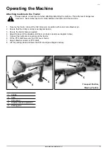
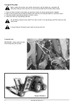
Page 18: ...is applied 2 Ensure moving parts become still then transform the machine into transport position by hydraulic control 3 Lift up the wings by operating hydraulics and lock in place 4 LIft the rear deck...

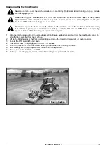
Page 19: ...Always start up the tractor PTO at a low RPM Build up to operating speed select a suitable forward gear proceed to cut grass 1 Hitch the machine as outlined in the previous section Ensure bystanders a...

Page 20: ...d roller should be adjusted Roller To adjust the height of the roller follow this procedure at both sides of the roller 1 Loosen Bolts B and C Note You do not have to remove these bolts half of the tu...

Page 21: ...ing brake and disengage the PTO An example of such emergency situation is the complete blockage of the machine in the field To clear out the blockage follow the safety steps described above and clear...

Page 22: ...t be checked daily Air pressure within pneumatic tyres must be maintained at 2 Bar Solid wheels must be checked for wear and damage and if necessary replaced immediately ENSURE BLADE ROTATION AND TIMI...

Page 23: ...icant Excessive grass debris build up around gearbox Remove grass etc from machine Blade bullets is scalping ground Mower too low Raise mower reset wheels Field is ridged Cut field at a different angl...

Page 24: ...ugh in oil seal area Replace or repair shaft Oil seal installed incorrectly Replace seal Oil seal not sealing in the housing Replace seal or use a sealant on outside diameter of seal Oil level too hig...

Page 25: ...40 standards Grease points Initially 25 hours 80 hours 400 hours PTO Shafts Roller height adjuster block 4x3 Roller height adjuster rod 4x3 Roller 2x6 Drawbar hitch 1 Rear deck pivot 4 Wing arm pivot...

Page 26: ...210621 15 23 24 66 7 17 16 22 22 6 34 94 79 8 93 79 82 76 25 103 7 42 76 81 67 6 59 32 90 84 95 97 49 1 89 93 79 79 94 78 90 5 78 92 98 95 80 81 76 83 89 9 11 11 52 10 84 1 MJ76 360 General Assembly...

Page 27: ...www major equipment com 23 72 104 30 72 75 75 104 30 17 16 6 20 21 60 75 18 75 62 76 81 69 18 16 104 72 88 77 77 84 84 77 19 77 85 27 53 87 77 84 101 63 20 81 76 69 22 60 21 61 60 75 87 77 44 77 84...

Page 28: ...www major equipment com 24 81 76 69 17 74 64 24 22 21 69 20 43 14 29 14 29 15 6 104 75 75 75 72 29 70 75 81 76 69 70 75 72 71 37 72 37 104 14 75 72...

Page 29: ...8 90 4 73 95 80 80 98 46 98 80 95 80 80 99 45 80 95 39 28 BRAKED STUB SHOWN ON DRAWG UNBRAKED MACHINES USE MJ30 560T AB12 ON CORRECT SIZE WHEELS MJ30 560T AB25 ON SMALL CHEAP WHEELS 47 48 105 55 2 96...

Page 30: ...MOUNT 2 46 MJ76 360 MD03 MUDGUARD MOUNT 2 47 MJ76 360 MD05 MUDGUARD MOUNT 1 48 MJ76 360 MD05H MUDGUARD MOUNT 1 49 TA HCM04 CABLE MOUNT 1 50 TA LGPLITL LGP LIGHT BRACKET LH 1 51 TA LGPLITR LGP LIGHT BR...

Page 31: ...www major equipment com 27 24 40 59 44 43 39 39 46 20 53 42 16 42 58 13 10 4 46 4 45 22 12 30 59 14 17 31 14 15 14 17 14 12 48 39 39 43 57 42 32 33 2 1 34 41 35 7 MJ76 Rear deck MJ76 360 RDGA01...

Page 32: ...www major equipment com 28 10 26 43 39 39 45 11 6 9 8 6 53 42 42 56 25 43 39 39 45 43 39 45 39 39 43 39 45 23 5 52 38 18 55 19 42 53 36 3 8 29 54 49 39 60 27 28 27 43 37 50 47 21 39 43 38 51...

Page 33: ...IGHT PIVOT BLOCK 8 28 8400RM HG77 M20 HEX ADJUSTER 4 29 RM RSN3 SHAFT COLLAR DIA 35 4 30 12HEX109 1 2HEX10 9 12 31 12x112FSKS 1 2 x1 1 2 FINE SOCKET HEAD 12 9 12 32 190000660 PLASTIC GUARD COVER 1 33...

Page 34: ...www major equipment com 30 42 61 46 49 41 41 45 25 15 5 6 6 49 47 60 44 55 44 21 17 41 45 48 23 58 44 35 14 37 33 61 18 34 13 18 14 3 44 58 1 2 43 36 16 16 9 32 63 MJ76 360 Left wing MJ76 360 WGGA02...

Page 35: ...www major equipment com 31 45 41 41 47 12 27 45 41 41 47 26 59 44 44 55 8 8 11 10 5 47 41 45 41 47 41 41 45 24 31 7 54 40 19 57 20 44 55 56 30 10 38 4 51 41 62 28 29 28 45 39 52 40 53 45 41 50 22...

Page 36: ...8400RM HG77 M20 HEX ADJUSTER 4 30 RM RSN3 SHAFT COLLAR DIA 35 4 31 111044 DIA 26 30mm INSERT 8 32 11402 HOSE CLIP 149 161 1 33 12HEX109 1 2HEX10 9 12 34 12x112FSKS 1 2 x1 1 2 FINE SOCKET HEAD 12 9 12...

Page 37: ...www major equipment com 33 42 61 46 49 41 41 45 25 15 5 6 6 49 47 60 44 55 44 21 17 41 45 48 23 58 44 35 14 37 43 36 33 61 16 18 34 13 18 16 14 3 44 58 1 2 9 32 63 MJ76 360 Right wing MJ76 360 WGGA01...

Page 38: ...www major equipment com 34 45 41 41 47 12 27 45 41 41 47 26 59 44 44 55 8 8 11 10 5 47 41 45 41 47 41 41 45 24 31 7 54 40 19 57 20 44 55 56 30 10 38 4 51 41 62 28 29 28 45 39 52 50 22 41 45 40 53...

Page 39: ...8 29 8400RM HG77 M20 HEX ADJUSTER 4 30 RM RSN3 SHAFT COLLAR DIA 35 4 31 111044 DIA 26 30mm INSERT 8 32 11402 HOSE CLIP 149 161 1 33 12HEX109 1 2HEX10 9 12 34 12x112FSKS 1 2 x1 1 2 FINE SOCKET HEAD 12...

Page 40: ...4 DOWTY WASHER 4 9 EFF14 1 4 F F CONNECTOR 1 10 EMM12 14 1 2 1 4 M M CONNECTOR 1 11 EMM14 1 4 M M CONNECTOR 2 12 EMMMT14 1 4 M M M CONNECTOR 1 13 MJ76 HOSE01 1 4 x 3000mm Str to Str 1 14 MJ76 HOSE02...

Page 41: ...62x30x17 25 2 2 35627 SEAL 35x62x7 1 3 55112 DIA 62 INT CIRCLIP 1 4 30x62 WIPE SEAL 915PG30 1 5 M12x30SK M12x30 SOCKET HEAD SCREW 4 6 M8x12SK M8x12mm SOCKET HEAD 12 9 1 7 RM 04NUT NUT WASHER WELDMENT...

Page 42: ...T HEAD 12 9 4 8 CW39174 DISC SPRING 39x17x4 YELLOW 2 9 M10 M10 NYLOC NUT 2 10 M10x30SKBH M10x30 SOCKET BUTTON HEAD 10 9 2 11 M16 M16 NYLOC NUT 2 Item Part No Description Qty 1 BLD 25025 C405 BLADE 250...

Page 43: ...on Qty 1 BLD 25025 OVL OVERLAP FOR BLADE 250xDia 25 2 2 XBLD BB 06 OVERLAP MOUNT 2 3 BS 2507 03 THREADED BLADE SUPPORT 2 4 1 2F 1 2 FINE NYLOC NUT 4 5 12x112FSKS 1 2 x1 1 2 FINE SOCKET HEAD 12 9 4 6 C...

Page 44: ...2 WS603672 WIDE ANGLE 2380 FIXED SLIP 1 Tractor input shaft 2 WS605911 WIDE ANGLE 2480 SBOR 1 Tractor input shaft 3 S5D03100C60001 CLAMP COLLAR PTO 2 Wing shaft ItemPart No Description 1 MW 24 30 Hei...

Page 45: ...omplete 2 22 153207 Drive in type lubrication fitting 3 23 365545 Plate 4 24 365722 Double yoke with lubrication fitting 1 25 020672 Lubrication fitting 1 26 161287 Inboard yoke 1 27 020617 Spring typ...

Page 46: ...203 Cap 9 61L5JA001 Hub 10 57116B1 Stud 11 57316B1 Nut 1 2 3 4 5 6 7 8 9 10 11 Bearing Kit Wheel kit hub 50 SQ 5 Stud braked axle stub to suit MJ30 560T AB14 Item Part No Description 1 56106203 Cap 2...

Page 47: ...l plug 1 11 8 6 7 00269 1 2 GAS breather plug 1 12 GB 03512 0300 housing 1 13 8 5 1 00029 circlip 40x 37 5x1 75 1 14 0 248 7500 adjusting washer 60 3x71 7 2 15 0 285 7500 adjusting washer 40 3x61 7 16...

Page 48: ...Washer 25x44x4 1 13 LF135 19 8 4 1 00993 Parallel Key B 10x8x30 1 14 M10x20SZP 8 1 1 00054 Bolts M10x20 4 15 8 5 2 00030 8 5 2 00030 Snap Ring 80x82 5x2 5 1 16 LF135 3 8 5 3 00955 Snap Ring SB 81 1 1...

Page 49: ...er LF135 2 1 13 8 4 1 00993 8 4 1 00993 Parallel Key LF135 19 1 14 8 1 1 00054 8 1 1 00054 Bolts M10x20 4 15 8 5 2 00030 8 5 2 00030 Snap Ring LF135 6 1 16 8 5 2 00955 8 5 2 00955 Snap Ring LF135 3 1...

Page 50: ...X80X10 4 7 0 244 7500 00 SHIM KIT 40 3x51 5 4 8 8 1 2 00785 BOLT M8X22 12 9 8 9 0 130 5001 00 CROWN WHEEL Z27 M5 64 1 10 0 110 7500 00 SHIM 65 3x79 7 2 11 8 6 5 00006 PLUG 3 8 GAS 2 12 8 6 6 00271 PLU...

Page 51: ...stered when sold to ensure that you receive the correct warranty cover and service bulletins To register your machine for warranty please go to the SALES SUPPORT section of our website www major equip...

Page 52: ...jor equipment com UK Office Major Equipment Ltd Major Ind Estate Heysham Lancs LA3 3JJ UK Tel 44 0 1524 850501 ukinfo major equipment com Netherlands Office Major Equipment Intl Ltd EU Postbus 29 NL 7...

Reviews: