background image


LUBRICATION 


Keep the column and both sides of the dovetail way well lubricated and free of dust or debris. Clean and remove dust, 

debris, and old lubricant as needed depending on frequency of use. After cleaning, reapply a verily light coating of 

lubricant. 


NOTE: Use any all-purpose oil, available at any hardware store). 


REQUIRED MAINTENANCE 


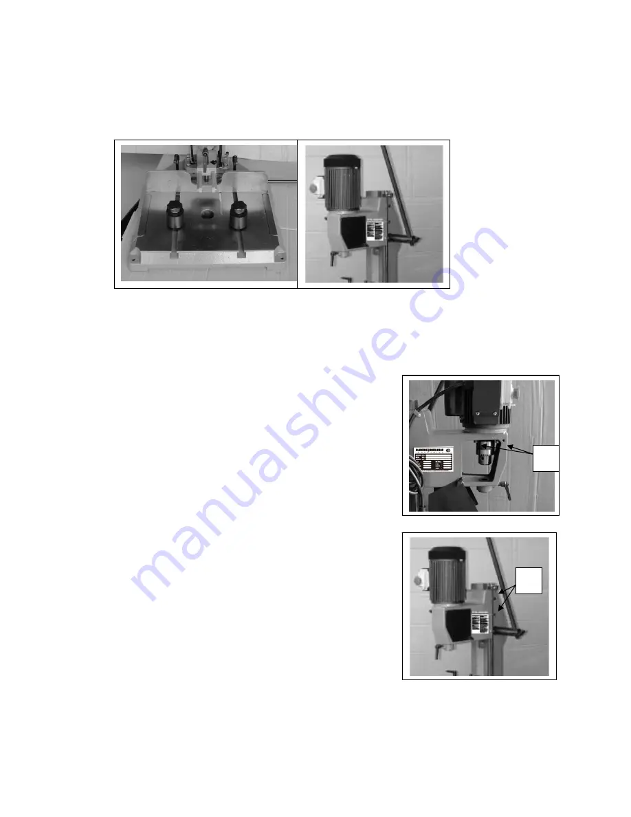
With use and normal wear over time, the motor assembly may loosen slightly.   
If you notice abnormal noise or vibrations, tighten the cap screws(A)   
( accessible behind the slide plates on both sides of the chuck), using the   
supplied Allen key. 


With use over time, some slight play may develop in head on the dovetail   
way due to wear. To eliminate play between the head and the dovetail way, 
loosen the lock nuts, and adjust the individual set screws as needed.   
Re-tighten the lock nut(s) once the adjustment has been completed. 


NOTE: Adjust only enough to eliminate play – do not over   
tighten as this can stiffen or restrict head travel, requiring 
more effort to complete the feed stroke and cause premature 
wear of the dovetail way. 


Summary of Contents for MI-77100

Page 1: ...MODEL NO MI 77100 OPERATING MANUAL ...

Page 2: ... DOWNFEED HANDLE 2 MOTOR 3 ON OFF SWITCH 4 GAS HEAD CYLINDER 5 EXTENSION WING 6 FENCE 7 BASE 8 FENCE LOCKING LEVERS 9 HEAD 10 WORKPIECE HOLD DOWN 11 TABLE ROLLER 12 CHISEL LOCKING LEVER 13 CHUCK KEY AND CHISEL HOLDER 1 2 3 4 6 7 8 12 13 11 5 9 10 ...

Page 3: ...allowing the user to install chisel and bit sets of either 5 8 4 supplied or 3 4 commonly available from other after market sources shank diameter This mortiser is designed to acommodate chisel and bit set sizes ranging from a minimum of 1 4 up to a maximum of 5 8 UNPACKING Carefully unpack and remove the mortiser and its components from the box and check for damaged or missing items as per the li...

Page 4: ...t on the fence INSTALL THE DOWN FEED HANDLE The four holes in the down feed shaft allow you to reposition the handle in the holes for better comfort and convenience 1 Loosen the lock knob A 2 Remove the handle B and reposition it as needed choosing the hole that provides the most comfortable handle angle 3 Re tighten the lock knob A to secure the down feed handle in position SERIOUS PERSONAL INJUR...

Page 5: ... lock knobs on the chuck cover C and slide the corresponding slide plate out of the way 4 Insert the supplied chuck key E and turn counterclockwise to open the chuck jaws and allow a drill bit to fit in 5 With a piece of plastic carboard or wood held between the tip of the bit and your finger E install the chisel and bit with the chip clearing slot facing either left or right and tighten the bit i...

Page 6: ...stock that has an even thickness 3 Loosen the fence locking levers and slowly advance the fence with the piece of wood towards the chisel If the face of the chisel sits flush against the stock the chisel is square Tighten the chisel locking lever and proceed with normal operation If the chisel does not sit flush 1 Loosen the chisel lock lever and manually turn the chisel until its face sits flush ...

Page 7: ...OLS CONNECTING TO A POWER SOURCE TO REDUCE THE RISK OF SHOCK OR FIRE DO NOT OPERATE THE UNIT WITH A DAMAGED POWER CORD OR PLUG REPLACE DAMAGED CORD OR PLUG IMMEDIATELY TO AVOID UNEXPECTED OR UNINTENTIONAL START UP MAKE SURE THAT THE POWER SWITCH IS IN THE OFF POSITION BEFORE CONNECTING TO A POWER SOURCE Once the assembly steps have been completed and the unit is safely secured to a work surface un...

Page 8: ...hisel to the bottom of your depth reference line then adjust the depth stop against the stop plate as shown B to prevent the chisel from lowering any further NOTE As a time saving convenience the upper stop can be set to control the upward travel of the head This feature allows you to save time by raising the bit only enough to clear the workpiece and allow you to reposition the workpiece without ...

Page 9: ...e part to be cut remains well visible set the workpiece on the table with the bit aligned with either The left end of the mortise if the chip clearing slot is facing left d The right end of the mortise if the chip clearing slot is facing right e NOTE To avoid overheating or damage to the chisel or bit do not position the slot against the blind end of the mortise as this would prevent the chips fro...

Page 10: ... fit of your tenon in the mortise Re adjust if needed MAINTENANCE PERIODIC MAINTENANCE Keep the machine clean and free of dust and woodchips Vacuum or brush off any loose debris and wipe down the machine and the table occasionally with a damp rag An occasional light coating of paste wax can help protect the table surface and reduce workpiece friction Ask your local distributor for suggestions on a...

Page 11: ...bnormal noise or vibrations tighten the cap screws A accessible behind the slide plates on both sides of the chuck using the supplied Allen key With use over time some slight play may develop in head on the dovetail way due to wear To eliminate play between the head and the dovetail way loosen the lock nuts and adjust the individual set screws as needed Re tighten the lock nut s once the adjustmen...

Page 12: ...ry For left hand operation the hub must be moved to the left side as follows 1 loosen the lock knob A and remove Handle B from hub D 2 unscrew the two set screws E and remove hub D from the pinion shaft 3 Install the hub D on the left side pinion shaft and secure with the set screws 3 Insert the operating handle into the hub D and lock it with knob A A B D E Right hand Left hand ...

Page 13: ...0 21 23 22 24 29 28 30 31 34 33 9 4 3 2 1 5 6 7 8 10 11 13 14 12 15 16 17 18 73 72 71 69 70 68 79 77 78 74 75 76 51 49 50 66 65 52 64 53 54 47 48 46 44 45 63 55 62 61 60 57 56 43 42 41 40 39 58 36 38 37 35 59 32 63 1 4 ...

Page 14: ... 1 MI 77100 21 CORD CLAMP 1 MI 77100 22 HEX NUT M6 3 MI 77100 23 CAP SCREW M6 X 20 3 MI 77100 24 PAN HEAD SCREW M5 X 10 3 MI 77100 25 SWITCH BOX 1 MI 77100 26 CABLE TERMINAL 1 MI 77100 27 POWER CORD 1 MI 77100 28 PAN HEAD SCREW M5 X 10 2 MI 77100 29 CONDENSER COVER 1 MI 77100 30 CONDENSER 1 MI 77100 31 PACKING 1 MI 77100 32 MOTOR 1 MI 77100 33 SCREW M4 X10 2 MI 77100 34 SWITCH 1 MI 77100 35 CHUCK ...

Page 15: ... MI 77100 64 LOCK KNOB M8 X 15 1 MI 77100 65 WORKPIECE HOLD DOWN 2 MI 77100 66 LOCKING LEVER M6 X 90 2 MI 77100 67 WASHER 1 MI 77100 68 FENCE 1 MI 77100 69 WORKPIECE HOLD DOWN SHAFT 2 MI 77100 70 NUT 1 MI 77100 71 SET SCREW M6 X 10 1 MI 77100 72 SLIDE BAR 2 MI 77100 73 SCREW M4 X 10 2 MI 77100 74 LOCK KNOB 2 MI 77100 75 WASHER 2 MI 77100 76 RUBBER ROLLER 2 MI 77100 77 BUSHING 2 MI 77100 78 WASHER ...

Reviews: