


32
ORI-46.650 Jupiter Magnetostrictive Transmitters
ORI-46.650 Jupiter Magnetostrictive Transmitters
33
1.6.5 HART Menu Items (cont.)
10
Display
Description
1
Enter Password
2
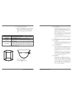
Blocking Distance
Distance below the reference point within which level is ignored.
(Operation is undefined when the liquid level is within the blocking distance.)
3
Level Trim
An offset value to be used to force the transmitter to output the exact Level or Distance. This
should only be used after all parameters have been entered correctly, and it has been con
-
firmed that the transmitter is tracking the correct level.
4
Ifc Level Trim
5
Failure Alarm Delay
Delay that can be added to loop failure condition.
This delay can be used to ignore nuisance, short term alarms.
Initial setting of this delay should be short, e.g., 1-2 seconds.
6
Sensitivity
Present Sensitivity (gain) of the instrument.
Default setting depends on the value in the probe memory and is suitable for most installa
-
tions.
Refer to I & O manual before adjusting.
7
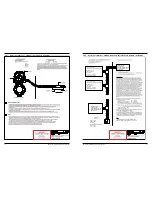
Adv Config Diagram
8
Threshold Settings
Allows for configuration of the various threshold settings. Automatic Threshold is used to
detect the strongest signal on the probe and should only be used when it is ensured that only
one medium is present. Fixed Threshold is used to detect the first valid signal on the probe
and should be used in cases where stratification can occur. For example, applications where
water bottoms can occur.
9
Analog Output
Certain parameters are password protected to limit access by the user. Parameters that
should never be changed by the user are protected with the Factory password. Some param
-
eters, intended for field use, that may be changed in special, controlled situations require the
Advanced password.
10
New User Password
Change password that is required to access user parameters.
11
Reset Parameters
Reset the device to factory calibrated settings.
If using a HART host, disconnect and then reconnect the host after performing the reset.
12
Probe Properties
Displays probe configuration parameters.
11
Display
Description
Lvl Thresh Mode
Selects the signal threshold control for measuring the upper level pulse.
Default setting depends on the value in the probe memory and is suitable for most installa
-
tions.
Refer to I & O manual before adjusting.
Lvl Thresh Value
Ifc Lvl Thresh Mode
Ifc Lvl Thresh Value
Upr Lvl Polarity
Selects the polarity for measuring the upper level pulse. Typically set to match the polarity
of the first portion of the sine-wave signal of a direct insertion float, or the first portion of the
M-shaped signal of an external mount probe.
Ifc Lvl Polarity
1.6.5 HART Menu Items (cont.)
12
Display
Description
1
Minimum Separation
Minimum distance that can be achieved between the magnets on adjacent floats when the
floats are touching each other.
2
Sensitivity
Present Sensitivity (gain) of the instrument.
Default setting depends on the value in the probe memory and is suitable for most installations.
Refer to I & O manual before adjusting.
3
Reset New Probe
Diagnostic
Clears the diagnostic that indicates a new probe has been attached. Updates the memory in
the transmitter to match the probe.
4
Lvl Thresh Mode
Selects the signal threshold control for measuring the upper level pulse.
Default setting depends on the value in the probe memory and is suitable for most installations.
Refer to I & O manual before adjusting.
5
Lvl Thresh Value
6
Upr Lvl Polarity
Selects the polarity for measuring the upper level pulse. Typically set to match the polarity
of the first portion of the sine-wave signal of a direct insertion float, or the first portion of the
M-shaped signal of an external mount probe.
7
Ifc Lvl Thresh Mode
Selects the signal threshold control for measuring the upper level pulse.
Default setting depends on the value in the probe memory and is suitable for most installations.
Refer to I & O manual before adjusting.
8
Ifc Lvl Thresh
Value
9
Ifc Lvl Polarity
Selects the polarity for measuring the upper level pulse. Typically set to match the polarity
of the first portion of the sine-wave signal of a direct insertion float, or the first portion of the
M-shaped signal of an external mount probe.
13
Display
Description
1
Enter Password
2
Elec Temp Offset
PCB temperature calibration value.
Refer to I & O manual before adjusting.
3
NAP Value
Advanced Password used for advanced troubleshooting.
4
Factory Reset
Reset the device to factory default settings.
If using a HART host, disconnect and then reconnect the host after performing the reset.
5
Factory Param 1
Factory parameter. Displayed for diagnostic purposes only.
6
Factory Param 2
7
Factory Param 3
8
Factory Param 4
9
Factory Calib
Read-Only Menu showing Factory Calibration Parameters.
10
Probe Properties
Displays probe configuration parameters.
14
Display
Description
1
Probe Conv Factor
Factory parameter. Displayed for diagnostic purposes only.
2
Probe Scale Offset
3
Drive+ Counts
4
Wait Counts
5
Drive- Counts
6
Calibration Date
Date on which the probe was calibrated.
7
Calibration
Location
Location where the probe was calibrated.