


28
ORI-46.650 Jupiter Magnetostrictive Transmitters
ORI-46.650 Jupiter Magnetostrictive Transmitters
29
1.6.5 HART Menu Items (contd.)
3
Display
Description
1
Enter Password
2
Tag
Text that is associated with the Field Device installation. This text can be used by the user in
any way. A recommended use is as a unique label to a plant that correlates to a Field Device
label, a plant drawing, or on a Control System. This variable is also used as a type of data link
layer address handle.
3
Long Tag
Functions exactly like Tag except the size is larger (maximum of 32 ISO Latin 1 characters).
4
Descriptor
Text that is associated with the Field Device. This text can be used by the user in any way.
There is no specific recommended use.
5
Final asmbly num
Number that is used for identification purposes, and is associated with the overall Field Device.
6
Date
Gregorian calendar date that is stored in the Field Device. This date can be used by the user in
any way. There is no specific recommended use.
7
Message
Text that is associated with the Field Device. This text can be used by the user in any way.
There is no specific recommended use.
8
Date/Time/Initials
When and by whom calibration was performed.
9
Factory Identity
A read-only screen that displays detailed manufacturer’s information about the transmitter, such
as Serial Number and hardware/software revisions.
4
Display
Description
1
Manufacturer
References a specific manufacturer, which is usually a company name, that is responsible for
the manufacture of this Field Device.
2
Product Name
Transmitter Trade Name.
3
Orion S/N
Serial number of the electronics contained in this transmitter.
4
Main Hardware Rev.
This revision corresponds to the electronics that are used in the Field Device.
5
Main Firmware Rev.
This revision corresponds to the software or firmware that is embedded in the Main Processor
of the Field Device.
6
CoP Hardware Rev.
This revision corresponds to the electronics that are used in the Field Device.
7
CoP Firmware Rev.
This revision corresponds to the software or firmware that is embedded in the CoProcessor of
the Field Device.
8
Cfg chng coun
Indicates the number of times the device’s configuration or calibration has been changed by a
host application or from a local operator interface.
9
Device ID
Uniquely identifies the Field Device when combined with the Manufacturer Identification and
Device Type. Therefore, this variable cannot be modified by the Host user.
10
Universal Revision
Revision of the Universal Device Description, to which the Field Device conforms.
11
Fld dev rev
Revision of the Field Device Specific Device Description, to which the Field Device conforms.
12
Software rev
This revision corresponds to the firmware that is embedded in the Field Device.
13
Num req pream
Number of Preambles required from the Host request by the Field Device.
1.6.5 HART Menu Items (cont.)
5
Display
Description
1
Enter Password
2
Measurement Type
The desired measurement mode of operation.
(Selection of Measurement Type may be constrained by the Probe Model.)
3
System Units
A menu that allows for setting the measurement units used by the transmitter.
4
Level Offset
Desired level reading when liquid surface is at the tip of the probe.
(Range is -50 feet [-15 meters] to +50 feet [15 meters])
5
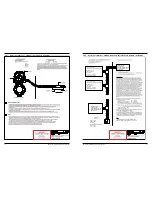
Basic Config
Diagram
6
Probe Properties
Displays probe configuration parameters.
6
Display
Description
1
Probe Model
Type of probe connected to the transmitter, as shown by the probe model number on the name
-
plate. Refer to the I/O Manual for additional information regarding different Probe Models.
2
S/N
Serial number of the probe connected to this transmitter.
3
Configuration
Probe configuration with sensor location.
4
Probe Type
Type of probe connected to the transmitter.
5
Probe Length
Distance from probe reference point to end of probe. Up to 35 feet (10.7 meters) maximum
depending on Probe Model. (Probe reference point is bottom of NPT Threads, top of BSP
Threads, or flange face for direct insertion, or end of probe head assembly for external mount.)
6
Temperature Rating
Temperature rating of the probe.
7
Vibration Rating
Vibration rating of the probe.
7
Display
Description
1
Enter Password
2
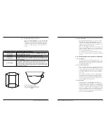
Vessel Type*
Shape of vessel. (Used when Measurement Type = Volume)
3
Radius*
Radius of the cylindrical/spherical portion of the vessel
Length
Horizontal length of the rectangular vessel or of the cylindrical portion of a vessel with elliptical
or spherical ends.
Width
Horizontal width of the rectangular vessel.
4
Custom Table
Allows for Custom Volume Strapping Table entry.
5
Vessel Diagram