


30
ORI-46.650 Jupiter Magnetostrictive Transmitters
ORI-46.650 Jupiter Magnetostrictive Transmitters
31
1.6.5 HART Menu Items (cont.)
8
Display
Description
1
Enter Password
2
PV is
An index location that indicates which Field Device dynamic variable has been mapped into
the Primary Variable dynamic variable.
3
PV 4 mA Set Point
Enter 4 mA point in level units
4
PV 20 mA Set Point
Enter 20 mA point in level units
5
PV Failure Alarm
Digital representation that tracks the Analog Output Number 1, under normal operating
modes.
Defines how the Analog Output will respond when the Field Device detects that the Analog
Output may not be tracking the associated Field Device Variable. NOTE- The Digital Value
representation may not be determinate.
6
Damping
A damping factor (0-10 seconds) may be added to smooth the output in the event of turbu
-
lence.
7
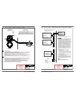
I/O Config Diagram
8
Variable Selection
Allows for selection of the Secondary Variable (SV), Tertiary Variable (TV), and Quaternary
Variable (QV). The analog 4/20 mA output will follow the PV.
9
Graph Ranges
Defines the limits of the vertical axes in DD/DTM graphs.
10
Probe Properties
-
Lvl 4mA Set Point
Defines the operational endpoint from which the Analog Value and the 0% point of the Per
-
cent Range are derived. In addition, the Lower Range Value defines an operational endpoint
from which the alarms associated with the Analog Value and the alarms associated with the
Digital Value representation are derived.
-
Ifc 4mA Set Point*
-
Thk 4mA Set Point*
-
Vol 4mA Set Point**
-
Lvl 20mA Set Point
Defines the operational endpoint from which the Analog Value and the 100% point of the Per
-
cent Range are derived. In addition, the Upper Range Value defines an operational endpoint
from which the alarms associated with the Analog Value and the alarms associated with the
Digital Value representation are derived.
-
Ifc 20mA Set Point*
-
Thk 4mA Set Point*
-
Vol 20mA Set Point**
*For ‘Interface & Level’ Measurement Type Only
**For ‘Volume & Level’ Measurement Type only.
1.6.5 HART Menu Items (cont.)
9
Display
Description
1
Enter Password
2
Language
Enables choice of language to be displayed on the LCD.
3
Status Symbol
Enables NE 107 Status symbol to be displayed on Home Screen.
4
Long Tag
Enables Long Tag to be displayed on the Home Screen.
5
PV Bar Graph
Enables a bar graph (displaying the Primary Variable in percent) to be displayed on the Home
Screen.
6
Display Setup
Diagram
7
Measured Values
A read-only screen that presents the various output values that can be displayed. (Available
outputs will depend on Measurement Type).
-
Upr Level
A read-only screen that presents the various output values that can be displayed.
(Available outputs will depend on Measurement Type).
-
Ifc Level
-
Upr Thickness
-
Distance
-
Volume
-
Fill Rate
-
Upr Echo Strength
-
Ifc Echo Strength
-
% Output
-
Analog Output
-
Elec Temp