


Mounting and installation
581E,5721/ 07/2006 MPR112_1
page 19/72
Version: 01
B
C
D
E
B
D
E
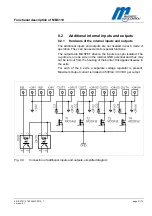
Fig. 4-3
Foundation plan, arrangement with different housing and passage widths
For the definition of „Passage“ (
DG
), refer to description on page 16.
NOTE!
When arranging further MPR units the same systematic applies as
described in Fig. 4-1 to Fig. 4-3.
•
MBC Lane Controller
Housing widths:
200 mm and 280 mm
A = 1400 mm
B = 250 mm
C = DG + 200 mm
D = DG + 240 mm
E = DG + 280 mm
•
MBC Lane Controller
Housing widths:
250 mm and 280 mm
A = 1400 mm
B = 300 mm
C = 770 mm
D = 785 mm
E = DG + 280 mm


