


LY71 Initial Setup Manual
10/16
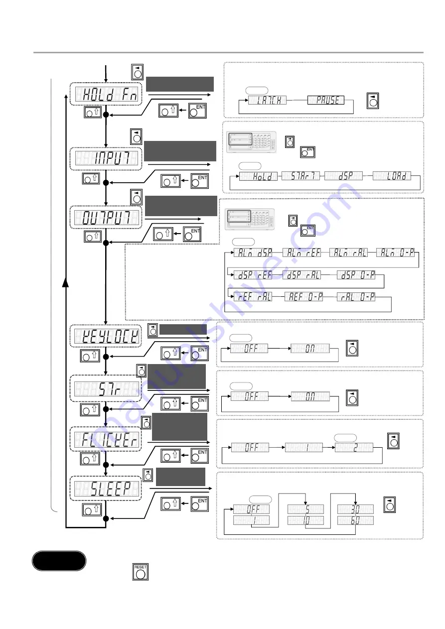
KEY LOCK
STORE
Current Value
Saving Function
FLICKER
Flicker control
function
SLEEP
sleep mode
Inhibition Weak
Inhibition Strong
off
6
.
When the advanced settings are complete, switch to the normal display.
Press key. This completes the initial settings.
.
Step 5
1 min.
none
10 min.
1h
5 min.
30 min.
set
off
set
off
HOLD Function
The hold function can be selected.
LATCH: Internal operations are not interrupted, and the displayed data is fixed
PAUSE: Suspend the operation of maximum and minimum values, etc.
Latch
Pause
Hold
Restart
Display data switching
Ref. input load
Alarm, Display
Alarm, Ref.
Alarm, Ref.-Alarm
Alarm, Zero point
Display, Ref.
Display, Ref.-Alarm
Display, Zero Point
Ref.-Alarm, Zero Point
Alarm, Zero Point
Ref., Ref.-Alarm
Key lock function can be set (to prevent accidental operation)
It is possible to save the display at power-off and display the value at power-on.
Flickering of the smallest digits can be suppressed in two stages
If no operation or scale movement is performed for a certain period of time, the
display will turn off.
Alarm: Alarm
Display: Display mode
Ref.: Home passing signal
Ref.-Alarm: Home Alarm
Zero point: Zero point passing signal
A
d
va
n
ce
d
S
e
tt
in
gs
default
default
default
default
default
default
default
INPUT
General-purpose input
If the option I/O (BCD unit, comparator unit) is connected, continue setting.
Function selection of general-purpose input (1 circuit each)
for display A and B axes
key for the axis to change
key to decide the selection
Display A, B axis
OUTPUT
General-purpose output
Function selection of general-purpose output (2 circuits
each) for display A and B axes
key for the axis to change
key to decide the selection
Display A, B axis
How to set up Advanced Settings (2/4)


