


(E)
2-11
LY71
2. Applied Operation
2-19. Compensating the Position
If the machine or other object where the measuring unit is mounted has some sagging and the position is
shifted, a compensation can be entered. Use the procedure below to measure the compensation value. Use
the linear compensation in the Installation Manual to set the compensation amount that is obtained.
2-19-1. Compensation
Generally a machine tool has its inherent geometric error. For example, with a knee type milling machine,
the knee is slightly tilted as the table moves and the horizontal component of this inclination is added to the
measuring unit displacement as an error. When the displayed value is obtained by adding an error compensation
corresponding to the actual displacement, the mechanical error is compensated for and a more accurate
display value is obtained for the actual displacement of the machine table, thus yielding more accurate
machining.
The unit is factory-set so that the compensation function is not activated.
If the compensation value is not known, set the compensation value to OFF in the “advanced settings”, and
redo the settings after measuring the compensation value.
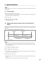
2-19-2. Linear Compensation
The linear compensation is set using the following process.
Measure the compensation (error) value
→
Set the linear compensation value (“Advanced Settings”)
Compensation amount :
up to
±
600
µ
m/m (can be entered in measuring unit input resolution units)
∗
Max.
±
1000
µ
m/m with the expansion function
The compensation amount is a displacement of 1 m for the millimeter operation. Input the value as millimeter
unit.
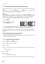
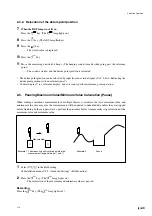
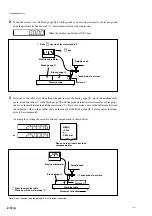
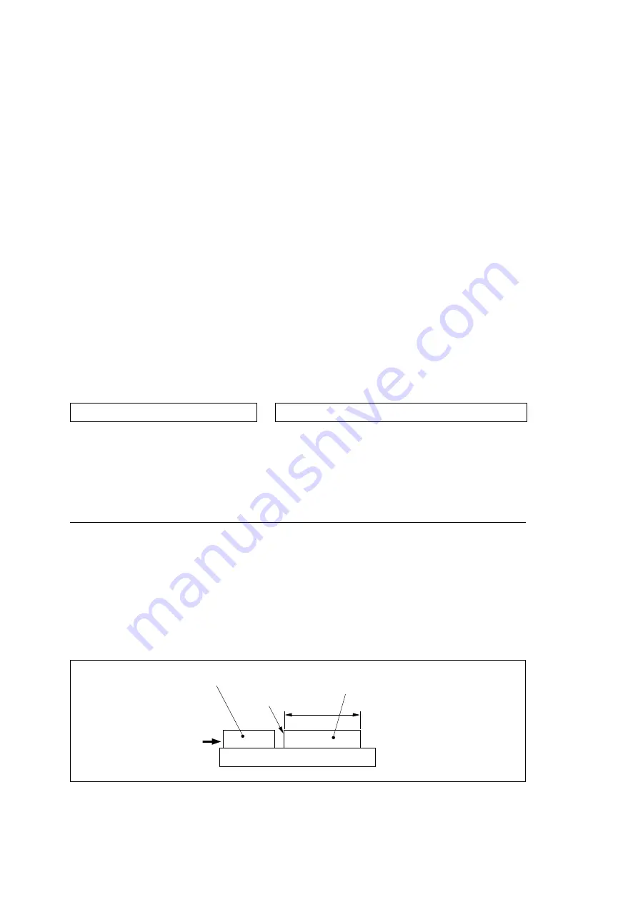
Error (compensation) measurement (Linear compensation)
Following is an example of machine error measuring procedures for determining the amount of compensation.
1
Place a block gauge
A
on the machine table until the block gauge
A
assumes the same temperature as
the machine table.
Then touch the surface B of the block gauge
A
with a block gauge
B
.
Example: L = 250 mm (L = 9.84250 in)
L
Block gauge
B
Surface B
Block gauge
A
Machine table
Contact block
gauges
A
and
B
Summary of Contents for LY71
Page 2: ...LY71...
Page 4: ...ii J LY71...
Page 5: ...LY71 J 1 1 1 4 4 2 1 1 4 1 1 4 1 2 A 3 2 16 1 2 1 2 15 2 C 1 3 1 2 3 ABS 4 5 4 1 1 0 005...
Page 6: ...1 2 J LY71 1 4 1 A 2 3 B 2 MAX C 2 MIN 1 5 1 2 1 4 1 7 2 15 9 1...
Page 8: ...1 4 J LY71...
Page 9: ...LY71 J 2 1 2 2 1 INC ABS 2 2 ABS INC P P INC P P 1 2 ABS 3 4 INC ABS C ABS ABS INC INC INC...
Page 11: ...LY71 J 2 3 2 3 2 7 REF 8 ABS 9 10 11 2 15 6 C 2 4 1 4 3 2 2 1 q w 2 q w...
Page 12: ...2 4 J LY71 2 2 5 1 4 3 2 2 6 4 3 2 7 4 3 2 8 4 3 4 3 9...
Page 13: ...LY71 J 2 5 2 2 9 4 3 ON 2 10 4 3 2 11 2 2 2 4 2 2 2 2 12...
Page 14: ...2 6 J LY71 2 2 12 2 ABS INC 1 1 A 2 A 3 B B A A B B A 1 B 1 2 13 1 B 2 A 4 3 ON...
Page 15: ...LY71 J 2 7 2 2 14 1 ON 4 2 2 3 4 5 6 7 8 1 2...
Page 19: ...LY71 J 2 11 2 18 2 18 1 0 2 18 2 600 m m 1000 m m 1 m 1 m 1 A B B L 250 mm L B B A 2...
Page 24: ...ii E LY71...
Page 28: ...1 4 E LY71...


