


12
�
�
C C
SOURCE
P I P
M E N U
OK
�
�������
���
���
���
�
�
�����
�����
����������
��
��
�
�
�
�
�
���������
������������
������������������
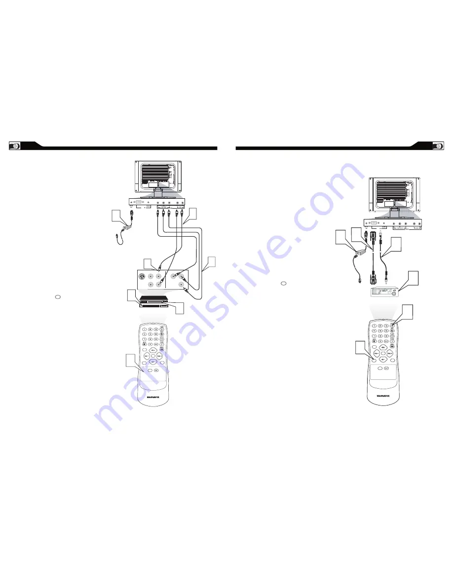
ACCESSORY DEVICE
EQUIPPED WITH COMPONENT
VIDEO OUTPUTS.
�����������
�����������
VGA
PC
Connect the component (Y, Pb, Pr) Video OUT
jacks from the DVD player(or similar device) to
the COMP(onent) VIDEO Input jacks on the
bottom of the LCD TV.
Connect the red and white AUDIO CABLES to
the Audio (left ad right) output jacks on the rear
of the accessory device to the AUDIO IN jack.
Connect the other end of the cable to the Audio
jack on the rear of LCD TV.
Plug the DC Adapter into the DC IN 16 V jack
on the LCD TV. Plug the power cable into an
outlet. Turn on the LCD TV and other
equipment.
Press the SOURCE button on the remote
control to select HD. HD will appear in the
upper left corner on the TV screen.
Insert a DVD disc into the DVD player and press
the PLAY button on the
DVD Player.
SOURCE
13
C
OMPONENT
(YP
B
P
R
) C
ONNECTIONS
C
omponent Video input provide the
highest possible color and picture
resolution in the playback of digital signal source
material, such as with DVD players.
1
2
3
4
5
Note: The accessory device must have an
component(YPbPr) output jack in order for you
to complete the connection on this page.
PC (M
ONITOR
) C
ONNECTION
T
his LCD TV can be used as a PC .
Your computer will have to be equipped with a
VGA type video output and VGA cable.
Connect one end of the VGA Video
cable (not supplied) to the Monitor (video)
output on the computer, while connecting the
other ends to the VGA INPUT jack on the LCD
TV.
Although audio connections are not required,
the LCD TV can reproduce the computers
audio out by an AUDIO ADAPTER to the Audio
output jack on the computer (if available) while
connecting the other ends of the Audio cables to
the PC AUDIO Jacks on the bottom of the TV.
Plug the DC Adapter into the DC IN 16V jack on
the LCD TV. Plug the power cable into an outlet.
Turn on the LCD TV and PC.
Press the SOURCE button until PC MODE
appears on the screen.
1
2
3
4
C C
SOURCE
P I P
M E N U
OK
�
�
�
Side Jack Panel
of Television
���
�����
������������
�����������
���������
�
�
�
VGA
PC
SOURCE


