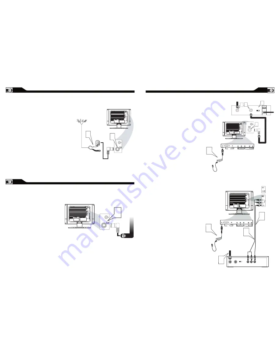
background image

9

A

NTENNA

 C

ONNECTION

If your antenna has a round cable
(75 ohm) on the end, then you’re ready to 
connect it to the LCD TV. If your 
antenna has flat, twin-lead wire (300 ohm), you 
first need to attach the 
antenna wires to the screws on a 300- to 
75-ohm adapter(not supplied).

Connect the antenna (or adapter) to one end 
of the supplied L-Adapter as shown, and con-
nect the other end of the 
L-Adapter to the TV jack on the side of 
the LCD TV.

Connect the Cable TV signal to one end of the 

supplied L-Adapter as shown, and connect the 
other end of the adapter to the TV jack on the 

LCD TV.

1

B

ASIC

 C

ABLE

 TV C

ONNECTION

2

1

Antenna

with 75

cable

Rear Jack panel of

Television

Outdoor or Indoor  Antenna

(Combination VHF/UHF)

OR


Twin-lead

wire to

300-75

adapter


The Cable  TV signal from

Cable Company

(75

coaxial cable)

Rear Jack panel of

Television

I

f you have a Cable Box, follow either set 

of  these steps to complete your 

connections.

Connect the Cable TV signal to the IN jack (or 
RF IN or CABLE IN) on the Cable Box.
Connect an RF coaxial cable (not supplied) to 
the OUT jack (or TO TV or RF OUT) of the 
Cable Box.
Connect the other end of the coaxial cable to 
one end of the supplied L-Adapter as shown, 
and connect the other end of the adapter to 
the TV jack on the LCD TV.
Plug the DC adapter into the DC IN 16V
jack on the LCD TV. Plug the power cable into 
an outlet. 
Set the Channel 3/4 (or Output channel) switch 
of the Cable Box to 3 or 4. Set the TV to the 
same channel. When watching TV 
programming, change channels at the Cable 
Box, not the LCD TV.

Cable Box with Audio/Video Out Jacks

This connection will supply Stereo sound to 

the LCD TV.

Connect the Cable TV signal to the 
IN jack (or RF IN or CABLE IN) on the Cable 
Box.

Using an RCA-type video cable (not 
supplied) connect one end of the video cable to 
the Video Out jack of the Cable Box.Connect 
the other end of the cable to the yellow VIDEO 
jack on the side of the TV.Video cables are 
usually marked with yellow and are available 
from Magnavox or electronics retailers. Video 
jacks on most equipment are yellow.

Using RCA-type, stereo audio cables (not 
supplied), connect one end of the cables to the 
left and right Audio Out jacks of the Cable Box. 
Connect the other end of that cable to the 
Audio jack on the side of the LCD TV.Audio 
cables are usually marked with red and white 
and are available from Magnavox or electronics 
retailers.The right 
audio jack is red and the left audio jack is white. 
Match the cable colors to the jack colors.

Plug the DC adapter into the DC IN 16V
jack on the LCD TV. Plug the power cable into 
an outlet. 

1

2
3

4

1
2

3

5

TO TV

CABLE

IN

� �

OUTPUT


CH

3          4

The Cable TV signal from

the Cable Company

75

Coaxial

Cable

Side Jack Panel of

T

elevision

DC  Adapter

Power

 Cable

VGA

PC

Cable Box with RF In/Out Jacks

This connection will not supply Stereo sound 

to the LCD TV. 

C

ABLE

 B

OX

 C

ONNECTIONS

S - VIDEO

CABLE

IN

TO

TV

VIDEO

OUT

L

R

AUDIO

OUT

3          4

OUTPUT

CH

VIDEO

Cable

TV signal 

Video Cable

Cable Box

Audio Cable 

Side Jack Panel

of  

T

elevision

AUDIO

DC  Adapter

Power

 Cable

VGA

PC

4

L-Adapter

L-Adapter

L-Adapter

A

combination antenna receives normal

broadcast channels (VHF 2–13 and UHF 14–69). 

Your connection is easy because there is only one 75 

Ω(ohm) antenna jack on the back of your TV, and that’s 

where the antenna goes.

Y

our Cable TV signal into your home may be a 

single,  75Ω(ohm)  cable.  If  so,  this  connection  is 

very  simple.  Follow  the  step  below  to  connect  your 

Cable TV signal to your new LCD TV.

8

Summary of Contents for 15MF500T - 15" Lcd Tv

Page 1: ...NNECTIONS FIRST TIME SETUP AND ANY OF THE FEATURES WE WANT YOU TO START ENJOYING YOUR NEW PRODUCT RIGHT AWAY CALL US BEFORE YOU CONSIDER RETURNING THE PRODUCT 1 800 705 2000 OR VISIT US ON THE WEB AT...

Page 2: ...lectronic equipment toys on the top of the cabinet Such items could unsuspectingly fall from the top of the set and cause product damage and or personal injury Wall or Ceiling Mounting The appliance s...

Page 3: ...PC Picture Controls 29 PC Audio Controls 30 Using PC PIP Picture In Picture Feature 31 Setting Up The PC Mode 32 General Information Trouble Shooting Tips 33 Care And Cleaning 34 Index 35 Regulatory...

Page 4: ...nscreen menu back to previous level inside the onscreen menu also press to exit the onscreen menu Volume button Press to increase or decrease the sound level also press to navigate left right in onscr...

Page 5: ...t the Cable TV signal to the IN jack or RF IN or CABLE IN on the Cable Box Using an RCA type video cable not supplied connect one end of the video cable to the Video Out jack of the Cable Box Connect...

Page 6: ...S VIDEO AUDIO VGA PC SOURCE S VIDEO CONNECTIONS The S Video connection on the rear of the LCD TV can provide you with better picture detail and clarity for the playback of accessory sources such as DB...

Page 7: ...ible color and picture resolution in the playback of digital signal source material such as with DVD players 1 2 3 4 5 Note The accessory device must have an component YPbPr output jack in order for y...

Page 8: ...MODE AUTO PROGRAM CHANNEL EDIT FACTORY RESET ENGLISH MANUAL FINE TUNE M E N U M E N U TUNER MODE CONTROL The Tuner Mode allows you to change the LCD TV s signal input to Cable or Air antenna It s imp...

Page 9: ...y pressing the CH or CH button Press the MENU button on the remote control to show the onscreen menu Press the CH button to highlight the INSTALL menu Press the VOL button to enter the INSTALL menu Pr...

Page 10: ...any of the options 1 2 Note The settings of the Personal smart sound mode can be adjusted in sound control within the onscreen menu The Personal mode is the only mode which can be adjusted by the use...

Page 11: ...out the sound being heard when sudden changes in volume occur during commercial breaks or channel changes Press the VOL or VOL button to adjust the item Press the CH or CH button to select and adjust...

Page 12: ...the following intense violence intense sexual situations strong coarse language or intensely suggestive dialog NC 17 No children under the age of 17 will be admitted This type of programming should b...

Page 13: ...to be blocked any higher level rating will also be blocked from viewing i e If R is selected to be blocked NC 17 and X will automatically be blocked Also when a rating is set to unblock any rating low...

Page 14: ...features are displayed on the screen Press the MENU button to see the onscreen menu Press the CH button to highlight the FEATURES menu Press the VOL button to enter the FEATURES menu Press the CH butt...

Page 15: ...TURE SMART PICTURE BRIGHTNESS CONTRAST AUTO ADJUST MANUAL ADJUST PHASE CLOCK HORIZONTAL VERTICAL MAIN CONTROLS PICTURE AUDIO FEATURES INSTALL SMART PICTURE BRIGHTNESS CONTRAST AUTO ADJUST MANUAL ADJUS...

Page 16: ...K AUDIO SMART SOUND SETTINGS STEREO VIRTUAL SURROUND AVL PERSONAL AUDIO SMART SOUND SETTINGS STEREO VIRTUAL SURROUND AVL TREBLE BASS BALANCE AUDIO SMART SOUND SETTINGS STEREO STEREO VIRTUAL SURROUND A...

Page 17: ...ote control to cancel or restore the volume If you have connected other equipment to the TV such as a VCR or DVD Player make sure the audio cables are connected securely between the TV and the other e...

Page 18: ...en TV Location To avoid cabinet warping cabinet color changes and an increased chance of TV failure do not place the TV where temperatures can become excessively hot for example in direct sunlight or...

Page 19: ...ul interference to radio communications However there is no guarantee that interference will not occur in a particular installation If this equipment does cause harmful interference to radio or televi...

Page 20: ...es All parts including repaired and replaced parts are covered only for the original warranty period When the warranty on the product expires the warranty on all replaced and repaired parts also expir...

Reviews: