EN
18
www.magmaweld.com
USER MANUAL | MANUEL D’UTILISATION | РУКОВОДСТВО ПО ЭКСПЛУАТАЦИИ | KULLANIM KILAVUZU
ID 65 PCA / ID 65 PCB
• The life of consumables depends on the material to be cut, cutting thickness, cutting length, cutting method,
appropriate distance to the material, air quality and blast frequency. If the frequency of blasting is high, the
consumable will wear out more quickly.
• When working with shielded consumables, the torch tip may touch the metal to be cut while cutting.
When working with unshielded consumables, a distance of 2-3 mm should be in between the part to be cut and the
torch.
• See 5.1 for detailed information on consumables.
Plasma arc forms immediately when the torch trigger is pressed.
Make sure the power supply is turned off when replacing plasma consumables.
There are 2 types of automation interfaces - digital and analog communication - used by the ID 65 PCA plasma
cutting machine.
Whereas, ID 65 PCB plasma cutting machine has only analog communication automation interface.
1) Digital Communication
Additional socket and card are added to the machine. Digital communication is achieved over Modbus by using
them. In addition to analog communication;
• Machine’s current can be adjusted remotely.
• Cutting current and gas pressure can be adjusted remotely according to the materials to be cut.
• Machine modes can be changed remotely.
• All error codes on the machine can be delivered to the automation interface. Thus, either the table is stopped or the
operator is warned.
The connector pins for signals to be used along the machine interface cable are depicted in the figure below. The
table contains information about the signals. The following table should be observed when the power supply is to be
connected to the CNC table or torch height controller with the machine interface cable:
: It shows that the switch is above.
Remote control will only be activated when using a mechanized torch. There is a connector for remote
control at the back of the machine. When the necessary connection is made to the connector on the back
of the power supply, it provides access to the arc voltage and yields a signal for arc transfer and plasma
initiation. See 5.2 for detailed information on automation wiring diagram.
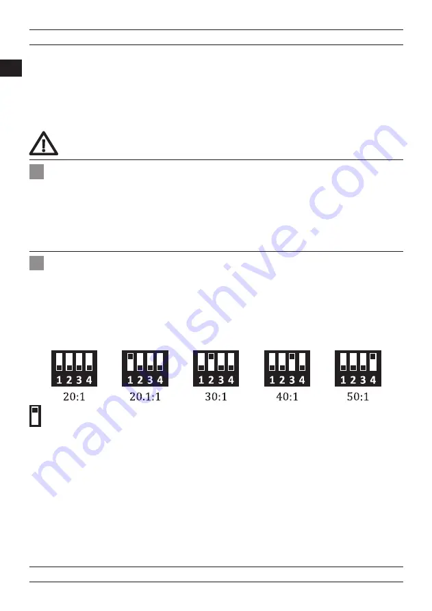
Voltage Divider Setting
The power supply has a five-position voltage divider.
Voltage information is changed with the help of the voltage divider. The voltage divider is set to 20:1 as
default. The table below shows the location of the DIP switches for voltage divider settings.
2.8 Remote Control
Installation
Ionized gas with high electrical conductivity is used in the plasma cutting process. The moment the plasma
torch is triggered, DC power is activated and a rapid flow of gas begins in the torch within a short time. This
DC power ionizes the gas in the torch and arc occurs. This arc which is narrowed and intensified by the torch,
is called pilot arc.
The pilot arc is forced out of the torch tip by high velocity gases. When it comes into contact with the metal
to be cut, the main current is formed and the cutting begins. The cutting process is continued by moving the
torch.
2.7 Pilot Arc
Summary of Contents for ID 65 PCA
Page 1: ...ID 65 PCA ID 65 PCB 90 444 93 53 magmaweld com info magmaweld com 90 538 927 12 62 USER MANUAL...
Page 39: ...RU 39 www magmaweld com USER MANUAL MANUEL D UTILISATION KULLANIM KILAVUZU ID 65 PCA ID 65 PCB...
Page 42: ...RU 42 www magmaweld com USER MANUAL MANUEL D UTILISATION KULLANIM KILAVUZU ID 65 PCA ID 65 PCB...
Page 60: ...RU 60 www magmaweld com USER MANUAL MANUEL D UTILISATION KULLANIM KILAVUZU ID 65 PCA ID 65 PCB...
Page 64: ...RU 64 www magmaweld com USER MANUAL MANUEL D UTILISATION KULLANIM KILAVUZU ID 65 PCA ID 65 PCB...
Page 109: ......
Page 110: ......
Page 111: ......


