background image

15

INSTALLATION INSTRUCTIONS

NOZZLE INSTALLATION

In order to install the snow nozzle bracket, align the four (4) small holes on the bottom of 

the bracket with the four (4) matching holes on the snow nozzle bracket base located 

on the PM-DMX1. Insert a fastener into each hole, and tighten to secure the snow nozzle 

bracket in place.

Once the snow nozzle bracket has been securely installed, the snow nozzle itself can be 

attached. Remove the bracket knob from one side of the nozzle, and the bracket screw 

from the other side. Align the two (2) threaded holes on the size of the nozzle with the 

two (2) holes located near the top of the snow nozzle bracket. Then re-install the bracket 

knob and bracket screw, and tighten to secure the nozzle in place.

Summary of Contents for PM-DMX1

Page 1: ...User Manual PM DMX1...

Page 2: ...formation contained within this document and or as a result of the improper unsafe insufficient and negligent assembly installation rigging and operation of this product DOCUMENT VERSION Due to additi...

Page 3: ...ited Warranty USA Only 5 Warranty Returns USA Only 6 Safety Guidelines 7 Maintenance Guidelines 9 Overview 10 Installation Instructions 11 Operation 16 System menu 17 DMX Setup 18 DMX Traits 20 Dimens...

Page 4: ...first contacting customer support Please do not discard the shipping carton in the trash Please recycle whenever possible BOX CONTENTS PM DMX1 device x1 Power Cord x1 Nozzle Bracket x1 CUSTOMER SUPPOR...

Page 5: ...anual D This is not a service contract and this warranty does not include any maintenance clean ing or periodic check up During the periods as specified above Magmatic Effects will replace defective p...

Page 6: ...t pre paid and insured to MAGMATIC in Los Angeles CA or a MAGMATIC Authorized Service Center The RMA number must be clearly written on the outside of the return box and a brief description of the prob...

Page 7: ...inal manufacturer s warranty and increase the risk of damage and or personal injury PROTECTION CLASS 1 FIXTURE MUST BE PROPERLY GROUNDED THERE ARE NO USER SERVICEABLE PARTS INSIDE THIS UNIT DO NOT ATT...

Page 8: ...nnectors are damaged and do not insert into the fixture securely and with ease NEVER force a power cord connector into the fixture If the power cord or any of its con nectors are damaged replace it im...

Page 9: ...d you need any spare parts please order genuine parts from your local MAGMATIC dealer Please refer to the following points during routine inspections A detailed electrical check by an approved electri...

Page 10: ...10 OVERVIEW Please Note The snow nozzle is not includ ed and is only shown here for reference...

Page 11: ...custom matrix designs to any metal truss structure or placing the fixture s on any surface a professional equipment installer MUST be consulted to determine if the metal truss structure or surface is...

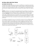
Page 12: ...terminal Check with a qualified electrician or serviceman if you do not completely and thorough ly understand the grounding instructions or if you are in doubt as to whether the appli ance is properl...

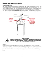
Page 13: ...te SAFETY CABLES of the appropriate rating to the safety cable loop SAFETY CABLE ALWAYS ATTACH A SAFETY CABLE WHEN INSTALLING THIS FIXTURE IN A SUSPENDED ENVIRONMENT TO ENSURE THAT THE FIXTURE WILL NO...

Page 14: ...ipod stand through the hole in the Omega bracket Tighten the nut onto the threaded bolt to secure the mounted device in place CAUTION MAKE SURE THAT THE TRIPOD LEGS AND ALL TELE SCOPING ELEMENTS OF TH...

Page 15: ...le and tighten to secure the snow nozzle bracket in place Once the snow nozzle bracket has been securely installed the snow nozzle itself can be attached Remove the bracket knob from one side of the n...

Page 16: ...nel and display screen located on the front of the device Generally the buttons func tions are as follows MENU is used to cycle through the main menu options UP DOWN are used to cycle through sub opti...

Page 17: ...Primary mode Sec Secondary mode DMST PrSE Primary secondary mode when DMX connection is lost BLMD Blackout mode when DMX connection is lost LAST Hold last state when DMX connection is lost Pan No Yes...

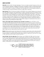
Page 18: ...uirements For DMX Operation The PM DMX1 can be controlled via DMX 512 protocol The DMX address is set on the front panel of the fixture Your unit and your DMX controller require a standard 5 pin XLR c...

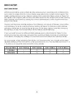
Page 19: ...ndividual fixture Setting all fixtures to the same DMX address will cause all fixtures to react in the same way In this case please note that changing the settings of one channel will affect all the f...

Page 20: ...speed 3 064 079 Pan 60 movement speed 4 080 095 Pan 60 movement speed 5 096 111 Pan 90 movement speed 1 112 127 Pan 90 movement speed 2 128 143 Pan 90 movement speed 3 144 159 Pan 90 movement speed 4...

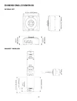
Page 21: ...21 DIMENSIONAL DRAWINGS NO BRACKET BRACKET INSTALLED...

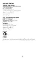
Page 22: ...ing Speeds 4 Button Control Panel LED System Menu Display 5pin DMX In Out AC Power Plug SIZE WEIGHT BRACKET INSTALLED Length 5 8 147 0mm Width 6 4 162 0mm Vertical Height 14 2 361 5mm Weight 5 7 lbs 2...

Page 23: ...23...

Page 24: ......

Reviews: