


-4-
CAUTION: HWG40 and HWG20 heaters with 24
volt electronic ignition come equipped for
installation of an automatic vent damper.
Heaters with 24 volt standing pilot must have
an additional or redundant gas valve installed.
Refer to the appropriate C.G.A. standards and
the instructions supplied with the automatic
vent damper.
1) Observe C.G.A. Standards B149.1 and B149.2
and local safety codes.
2) Ensure that the service switch located on the
motor housing of the automatic vent damper is
at the “AUTOMATIC OPERATION” position.
The “HOLD DAMPER OPEN” position is for
service only.
3) The automatic vent damper must be wired
according to the instructions in section 4.10
ELECTRICAL CONNECTIONS.
Failure to do
so will result in incorrect operation of the
automatic vent damper and a potentially
dangerous condition.
4) Read the manufacturer’s manual provided with
the automatic vent damper and ensure that all
instructions are followed.
4.6 POWER VENTER
The following instructions, and all instructions in
this manual pertaining to power venters, refer to
the Magikist model HWG-PV6B-24 (for the
HWG40) or the HWG-PV4B-24 (for the HWG20)
power venters. Other power venters are neither
approved not tested for use with the HWG40 or
the HWG20 heaters.
1) Observe C.G.A. Standards B149.1 and B149.2
and local safety codes.
2) The power venter must be wired according to
the instructions in the separate document
HWG-PV Power Venter Wiring Instructions.
Failure to do so will result in incorrect
operation of the power venter and a
potentially dangerous condition.
3) Read the manufacturer’s manual provided with
the power venter and ensure that all
instructions are followed.
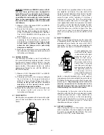
4.7 FLOW SWITCH
Most heaters are supplied with a flow switch which
you will find installed on the water inlet of the
heater.
Figure 4.7.1
If your heater was supplied without a flow switch,
one
must
be installed on the water inlet of the
heater for correct operation of the heater. The flow
switch must be a single pole, single throw,
normally open switch capable of switching a
minimum of 1 amp at 24 VAC. The switch must
also have minimum flow rate of 1.0 U.S. gpm. For
most applications where the high pressure output
of a pump is to be fed directly through the flow
switch into the water inlet of the heater,the
maximum pressure and flow rating of the flow
switch must meet or exceed the operating
pressure and gallons per minute (GPM) of the
pump.
4.8 INLET PLUMBING
When facing the front of the heater, the water inlet
is located on the left, top side. If a flow switch was
provided with your heater, the inlet is 3/8” FNPT
connection. If a flow switch was not provided with
your heater, the inlet is a 3/4” MNPT connection.
In most applications, the
water inlet of the heater
is connected to the high
pressure outlet of a
pump. In such cases,
the direct connection to
the water inlet of the
heater from the pump
must be made with high
pressure hose rated for
the operating pressure
of the pump and the
water outlet temperature
of the heater. Your
heater is normally supplied with a short length of
high pressure hose connected to the water inlet of
the heater that you may use to attach to your inlet
plumbing to.
Rigid piping must never be
directly connected to the heater due to the
potential damage that may result from pump
vibration being transferred to the heater.
The plumbing to the water inlet of the heater
should be sized for the flow rate desired in order
to prevent pressure loss. There should be no
unnecessary restrictions in the inlet plumbing.
Length should be kept to a minimum as should
the number of elbows and joints. Teflon tape
should be used to seal all joints.
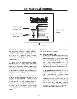
4.9 OUTLET PLUMBING
When facing the front of the heater, the water
outlet is located at the front, slightly to the right of
the center on the HWG40 the HWG20. The water
outlet is a 3/8” FNPT swivel connection.
Figure 4.8.1
WATER
OUTLET
PROSAFE II CONTROL
Flue
Sensor
Temp
Sensor
Flow
Switch
WATER
INLET
PROSAFE II CONTROL
Flue
Sensor
Temp
Sensor
Flow
Switch
FLOW
SWITCH
PROSAFE II CONTROL
Flue
Sensor
Temp
Sensor
Flow
Switch
WATER
OUTLET
PROSAFE II CONTROL
Flue
Sensor
Temp
Sensor
Flow
Switch
WATER
INLET
PROSAFE II CONTROL
Flue
Sensor
Temp
Sensor
Flow
Switch
FLOW
SWITCH
PROSAFE II CONTROL
Flue
Sensor
Temp
Sensor
Flow
Switch
Summary of Contents for HWG20
Page 2: ...this page was intentionally left blank...
Page 4: ...this page was intentionally left blank...
Page 23: ...20...
Page 24: ...21...


