Magikist HWG20 Instruction Manual Download Page 19

-15-

10.1 COIL CONDENSATION

During the operation of your heater, you may
notice water in the base of the heater or you may
hear the sizzling of water drops falling on the
flames of the main burner. This collection of water
or “dripping” of water is typical in the operation of
all steel coil heaters. It is caused by the products
of gas combustion which produce gaseous carbon
dioxide and water vapour. The water vapour
condenses on the coils which have cold water
running through them. The lower the temperature
of the incoming water, and the higher the rate of
combustion and/or the higher the relative
humidity, the more “drip” that occurs. Over a
period of time this tends to decrease.

If you suspect that the water in the base of the
heater is not from coil condensation, turn the
heater off such that the main burners are not lit
and run water through the heater. The “dripping”
of water from coil condensation will stop after a
short period of time.

10.2 COIL SCALING

Scale build-up in the heater coil can reach a point
where the recovery rate of the heater is reduced
and/or the flow of water through the heater is
restricted. Use of hard water through the heater
tends to accelerate scale build-up. Should scale
build-up reach a point where the operation of the
heater is affected, descaling with an approved coil
cleaner may be required. See section 8.4
CLEANING HEATER COIL OF SCALE for more
information.

10.3 FREEZING CONDITIONS

Freezing conditions can result in severe damage
to the heater coil. Coils must be drained
completely with compressed air or have anti-
freeze run through them if they are exposed to
freezing weather. Note that heater coils installed
in a heated building can still freeze. If the building
has a negative pressure cold air will be drawn
down the chimney and could freeze the top of the
coil. This can normally be prevented by the use of
an automatic vent damper.

10.4 USE OF ACIDS

If acids of any type are used then a form of
downstream chemical injection or suitable check
valve should be used to protect the coil.

10.5 COIL TEST

After manufacture each coil is hydrostatically
pressure tested to 3500 PSI. Each heater also has
a final hydrodynamic leak test performed after
final assembly (with all fittings installed) before the
heater leaves the factory.

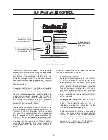
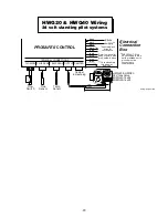
10.6 TERMINAL CONNECTIONS TO 

P

RO

S

AFE

IIII


Except for the FLOW SW connection, the

P

RO

S

AFE

II

uses lockable polarized plugs for all

it’s terminal connections. To remove a plug you
must press down on the locking pin and then pull
the plug out. Never use excessive force to remove
the plugs. When reinserting a plug, simply align
the plug with the correct terminal connection and
insert. Plugs are polarized and will only fit into the
correct terminal connection.

10.0  HELPFUL INFORMATION

Connections to ProSafe II


Summary of Contents for HWG20

Page 1: ...DEL HWG40 MODEL HWG20 GAS FIRED COMMERCIAL INDUSTRIAL PRESSURE WASHER HEATERS INSTRUCTION MANUAL V3 02 For heaters equipped with ProSafe II control and 24V electronic ignition HSI or 24V standing pilo...

Page 2: ...this page was intentionally left blank...

Page 3: ...INDICATOR 10 6 4 REQUEST FOR HEAT INDICATOR 10 6 5 PURGE DELAY ON INDICATOR 10 6 6 FLOW ON INDICATOR 10 6 7 THERMOSTAT INDICATOR 10 6 8 EXTERIOR CONTROL INDICATOR 10 6 9 FLUE STATUS INDICATOR 11 6 10...

Page 4: ...this page was intentionally left blank...

Page 5: ...rovide safe and effective control of the heater The PROSAFE II control provides visual status to the operator of the heater through a front panel display on the heater Should some condition arise whic...

Page 6: ...injury Always keep clear of the spray nozzle Do not direct discharge stream at people or electrical apparatus 3 Always keep clear of moving belts and pulleys 4 Never disconnect high pressure hose dur...

Page 7: ...t outage should occur the floor areas should be vented and blown clear before relighting the pilot IMPORTANT Licensed gas installer MUST ensure 3 5 W C for natural gas heaters or 11 W C using an exter...

Page 8: ...w normally open switch capable of switching a minimum of 1 amp at 24 VAC The switch must also have minimum flow rate of 1 0 U S gpm For most applications where the high pressure output of a pump is to...

Page 9: ...uctions later on in this section The second wiring configuration is used when installing the heater without a Magikist control panel If 24VAC is not available you will need to mount the supplied trans...

Page 10: ...tallations that do not utilize a Magikist control panel and another component of your system requires the flow switch for some control aspect the black wire and the EXT FLOW blue wire may be used to d...

Page 11: ...ions on adjusting the flow switch If the DAMPER OPEN indicator does not follow the steps below refer to section 11 0 TROUBLESHOOTING 1 Turn on the high pressure pump or other source supplying water to...

Page 12: ...nob from pilot to on initially due to air inside the gas valve If this occurs repeat the steps in section 5 5 4 If the water inlet of the heater is connected to a high pressure pump start the pump and...

Page 13: ...h affect the operation of the heater are detected and displayed to the operator by the PROSAFE II control Following is a description of the indicators and their function on the PROSAFE II control 6 1...

Page 14: ...flashing slow the PROSAFE II control is indicating a warning that there is water flow through the heater and that it has been continuous for at least 10 minutes This warning is strictly for informatio...

Page 15: ...ose the damper only after there is no water flow for a preset period of time This eliminates the on off cycling a damper experiences in high pressure wash systems where wash guns are opened and closed...

Page 16: ...nt the heater from firing Warning conditions should be attended to promptly in order to ensure the continued safe operation of the heater Should a warning condition arise the indicator light that rela...

Page 17: ...ing another pilot trial period The SmartValve is a continuous retry control Thus it will continuously repeat the pilot trial period followed by the 5 minute delay period until the pilot is successfull...

Page 18: ...burner 9 3 CARE OF MAIN BURNERS Due to condensation from heater coils dripping on the burners a scale build up may occur in the burner jet orifices To remove the burner bar from the heater turn off th...

Page 19: ...an approved coil cleaner may be required See section 8 4 CLEANING HEATER COIL OF SCALE for more information 10 3 FREEZING CONDITIONS Freezing conditions can result in severe damage to the heater coil...

Page 20: ...out frequently standing pilot heaters only Heater is in location that is too drafty Pilot assembly requires service Relocate heater See section 4 1 LOCATION Have gas service personnel check operation...

Page 21: ...ue are at or near freezing Take necessary steps to increase temperature in flue so that coil does not freeze DAMPER OPEN indicator is always on If an automatic vent damper is not installed then this i...

Page 22: ...rature sensor if necessary Temperature setting display flashes E21 and THERMOSTAT indicator is flashing Communicaton problem with temperature sensor short Check connection of temperature sensor to PRO...

Page 23: ...20...

Page 24: ...21...

Page 25: ...SENS TEMP SENS FLOW SW OUTPUT DAMPER brown black 24vac supply black black purple purple blue grey yellow white Refer to manual for wiring of purple blue grey yellow white Duplicate black wires for co...

Page 26: ...SENS FLOW SW OUTPUT DAMPER brown black black black purple purple blue grey yellow Refer to manual for wiring of purple blue grey yellow white Duplicate black wires for convenience Electrical Connecti...

Page 27: ...2 Depth 32 Height without draft hood 46 Height with draft hood 66 3 4 Shipping weight 418 lbs HWG20 Type Instantaneous steel coil Gas supply Natural N models LP P models Coil specifications 3 4 I P S...

Page 28: ...ation any warranties or merchantability or fitness for a particular purpose and all such warranties are hereby disclaimed and excluded by the manufacturer Repair or replacement of defective products a...

Reviews: