Page 44
4.3. Replacing Parts
For any spare parts that are required, please contact either your supplier or the manufacturer
directly. You will either need the
serial number
or: a) model name; b) the gas type; c) the
imitation fuel type; d) the type of control.
Only approved parts should be used.
4.3.1. Pilot Assembly Replacement
NOTE:
If any part of the pilot assembly becomes faulty then the whole pilot
assembly will need changing.
1. Remove the HT lead from the end of the
electrode.
2. Cut the cable tie wrap.
3.
Using M9 spanner undo the
thermocouple connection from behind
the control valve
4. Using M10 spanner undo the pilot feed
pipe nut at the pilot assembly.
5. Remove the pilot lint guard and undo the
pilot assembly securing screws and
withdraw the pilot assembly.
6. Refit in reverse order ensuring that the
lint guard is fitted.
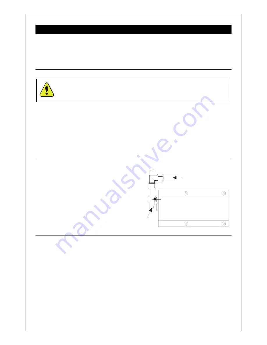
4.3.2. Injector Replacement
1. Undo the compression nut on the gas
feed pipe to the injector (see
Figure 72
).
2. Undo the valve securing screw/s and
disengage the gas feed tube out of the
injector.
3. Unscrew the injector from the venturi
cover.
4. Replace in reverse order ensuring that
the replacement jet size (marked on the
jet) is as given on the data badge.
Venturi Cover
Injector
Compression nut
Gas Feed from Valve
Figure 72
4.3.3. Control Valve Replacement (Mertik GV34)
1. Disconnect the pilot feed pipe, the main
gas feed pipe and the thermocouple
connection from the back of the valve.
2. Pull out the HT lead connection from
under the electrode and cut the cable tie
wrap.
3. Remove the valve securing screw/s and
withdraw the valve.
4. Refit the new valve in reverse order
ensuring that the valve spacers (on
Mertik valve) are in place.
5. Roll up the excess length of HT lead and
secure it to the rolled up thermocouple
cable with a new tie wrap.


