035-000029-001
Page 31
HHA IOM 1.4 10/11/2021
EXPANSION VALVE PIPING — Distributor nozzles and expansion valves sized for acceptable per-
formance for a range of conditions are factory supplied. Use the AHU (air-handling unit) selection
program in the electronic catalog to select optimal nozzle sizes.
Circuiting selection should result in a circuit loading of 0.8 to 2.0 tons per circuit at design load. Cir-
cuit loading must be evaluated at minimum load to ensure that it does not drop below 0.6 tons per
circuit. Solenoid valves may be used, if necessary, to shut off the refrigerant supply to individual ex-
pansion valves to maintain adequate coil circuit loading.
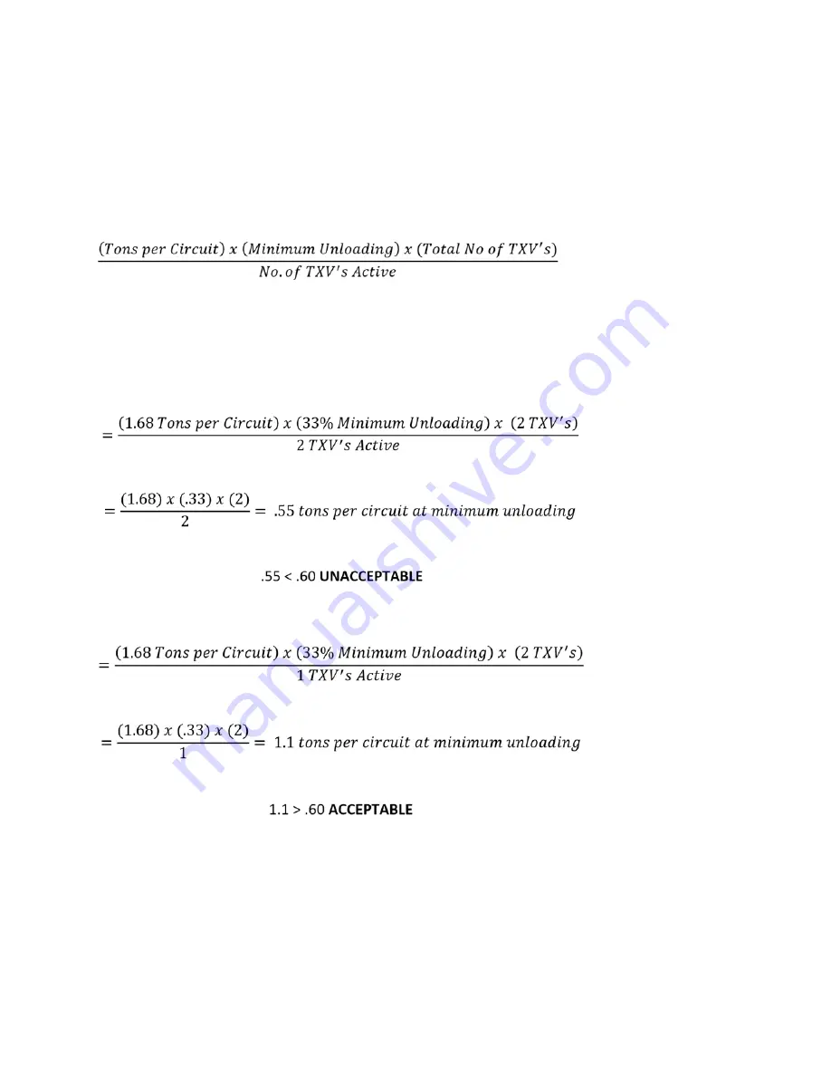
Compressor minimum unloading and TXV quantity is necessary to determine minimum tonnage per
circuit.
Minimum Unloading Equation:
Example:
Condensing Unit: 38ARS012
Minimum Unloading:
33%
Coil:
6 row, 11 FPI, Half Circuit
Coil Tons per Circuit:
1.68
Total TXVs:
2
In the first example we will determine the tons per circuit when both TXVs are active and the
compressor is unloaded to its minimum of 33%
If we install a liquid line solenoid valve before one of the TXVs and close it so that only one TXV
is active when the compressor is unloaded to its minimum of 33%, we see the following:
There are three different options to control tons per circuit when using an unloading compressor. The first
is to use drop solenoid valve control as illustrated above and let the suction cutoff unloaders “ride” with the
load. The second is to use drop solenoid valve control as illustrated above with electric unloaders and let
the control algorithm determine the combination of solenoid valves and unloaders to limit tons per circuit to
acceptable limits. The third is to limit the minimum amount of unloading so that tons per circuit is within
acceptable limits.
TXV SENSING BULB—sensing bulb for TXV is shipped coiled up inside cabinet. Remove coil connection
panel, route sensing bulb out through suction line hole in panel, reinstall panel. Locate sensing bulb on
horizontal section of suction line , and attach to tubing using copper plated strap. Attach sensing bulb be-
tween but no lower than the 2-o’clock and 10-o’clock positions. Make sure that there is good contact be-
tween the bulb cylinder and tubing. INSULATE the sensing bulb to insure that it reads the temperature of
the suction line. For dual-circuit DX coils, make sure to locate the sensing bulb on the correct suction line.
INSTALLATION-Piping (cont’d)
Summary of Contents for HHA Series
Page 2: ...035 000029 001 Page 2 HHA IOM 1 4 10 11 2021 THIS PAGE INTENTIONALLY LEFT BLANK...
Page 55: ...035 000029 001 Page 55 HHA IOM 1 4 10 11 2021...
Page 56: ...035 000029 001 Page 56 HHA IOM 1 4 10 11 2021...
Page 57: ...035 000029 001 Page 57 HHA IOM 1 4 10 11 2021 B...
Page 58: ...035 000029 001 Page 58 HHA IOM 1 4 10 11 2021 D...
Page 63: ...035 000029 001 Page 63 HHA IOM 1 4 10 11 2021 THIS PAGE INTENTIONALLY LEFT BLANK...


