Maggi 16271400 Use And Maintenance Manual Download Page 19


Pag. 12 

WOOD SHAVINGS REMOVAL 
The wood shavings and waste resulted during the work cycle should be removed in compliance with the stan-
dards in force in the Country of Use of the machine. 
Please contact the competent bodies in the Country of Use, in order for them to provide you with the relevant 
standards in force. 

Warning: 

the machine is intended for aspiration, but it is not provided with a vacuum 

system; the customer should provide this device, based on the processed material 
and frequency with which the machine is used. Please install a suitable system, able 
to maintain the dust concentration below the TLV provided in the Country of use.


Attention: we strongly recommend that the connection to the electrical power supply is 
done by technical qualified personnel only. 

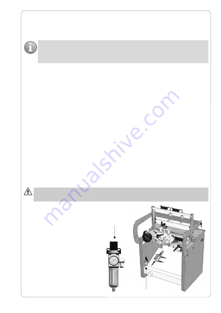
14.2   PNEUMATIC CONNECTION 
Connect the Filter regulator unit with the air 
line through a rubber or nylon hose with a 
minimum inside diameter of 8 mm.


If the pipe length exceeds 5/6 metres it is ad-
visable to increase the inside diameter to 10 
mm, you are also recommended to install a 
supply shut-off valve on the machine with 
manual control complete with air relief. 
The Filter purifies the air from dust and hu-
midity protecting the valves or seals in the 
pneumatic cylinders. 

14.3 MACHINE  STARTING 
The work station and control panel are on 
the machine electric panel. The operator 
places the pieces on the work table after 
adjusting the stops. 

6


14.   MACHINE CONNECTION TO EXTERNAL POWER SUPPLY


After machine assembling and installation, connect it with: 



Electrical power supply 



Pneumatic power supply 



Dust suction system 

14.1  CONNECTION TO ELECTRICAL POWER SUPPLY 
To gain access to the machine electric system, open the main board door by loosening the screws on the front 
of it. We recommend not to connect the machine to the electrical power supply until it is not correctly placed in 
the right place. Before connecting the machine to the electrical power supply, it is necessary to verify that the 
electrical system corresponds to the following necessary power and safety requirements: 



Grounded equipotential electrical system 



Presence of fuses or protection switches against short circuits on every conducing cable R-S-T, except 
the grounded one 



The electrical power system must be in conformity with CEI 64.8 (CENELEC HD 384, IEC364-4-41) rules 



Voltage and frequency for the motors are specified on the plates placed on them 



Connect the power supply cable to R-S-T terminals 



Automatic protection devices installed upstream respect to the machine; they have to be coordinated to 
guarantee the automatic break according to above mentioned rules. 

The electrical connection is done by three-phase plug (or single-phase plug, depending on the panel). 
The cable for ground connection is yellow-green. 
The tolerance of admissible voltage is +/-10% 
When voltage is applied to the electrical power supply, check that the spindles rotation direction is the one writ-
ten in the plate placed on the head (Black=Right; Red=Left). 
If the rotation direction does not match the one impressed in the plate, please invert the connection cables to 
three phase power supply. For any information please see the electrical diagrams included in this manual. 

Summary of Contents for 16271400

Page 1: ...NG SYSTEM 21 PRESTIGE WOODWORKING MACHINERY ORIGINAL USE and MAINTENANCE MANUAL THIS MANUAL SHOULD ALWAYS BE KEPT NEAR THE MACHINE FOR FUTURE REFERENCE MACHINE CODE MANUAL CODE REV EN 16271400 0000821...

Page 2: ...This page intentionally left blank...

Page 3: ...ease consult only the information regarding the particular configuration of your machine This manual was prepared exclusively for use by its customers ensuring that this is the most up to date documen...

Page 4: ...This page intentionally left blank...

Page 5: ...es that the machine is in compliance with all provisions pursuant the following directives 2006 42 CE Machinery Directive 2004 108 CE Electromagnetic Compatibility and represents the technical file Ce...

Page 6: ...THE SPINDLE HOLDER HEAD 15 5 0 90 DRILLING USING THE REFERENCE STOP 15 6 USE OF THE LONG FENCE 1 5 1 5 mt STANDARD 15 7 USE OF THE REFERENCE PIN OPTIONAL 15 8 USE OF THE TRIANGLE FOR 45 CORNERS OPTION...

Page 7: ......

Page 8: ...o use or maintain the machine you should always specify the model and serial number on the plate It is strictly forbidden to remove this plate or to change the data on it On the boring machine describ...

Page 9: ...ith its trasmission system 3 clamp group for vertical blocking of the work piece 4 pneumatic system for head positioning and head feed 5 reference stops to obtain the same drilling distance from verti...

Page 10: ...using the pedal The operator should always keep in mind the possible consequences that may occur when going near the dangerous areas such as boring area clamps operation range If you are not using the...

Page 11: ...and are used to identify each part of the machine One of the plates contains the serial number and identification data of the machine itself Safety clamps They remain on top of the working table or o...

Page 12: ...on hazard damages caused by noise hazards caused by dust emission In order to prevent risks while placing installing adjusting using performing the routine and extraordinary maintenance operations ple...

Page 13: ...ROPER USE Any action performed without following the instructions mentioned in this manual is considered improper Additional information We do NOT RECOMMEND leaning or placing tools above the machine...

Page 14: ...eight any difference in level should comply with the building regulations If the machine should be placed on a raised structure the slab support system should have the capacity to sustain the weight o...

Page 15: ...machine correctly you must ensure the clearance areas indicated belowi Pag 8 4 mt 12 MACHINE INSTALLATION AND CHECK PROCEDURE The boring machine is packaged in a wooden crate Given the size of the pa...

Page 16: ...ibed above can be performed using the tools purchased together with the machine Assemble the back reference stop as depicted in the figure Then assemble the clamp goup Insert the clamp unit assemble t...

Page 17: ...Pag 10 Assemble the squares of the bench on the plane Insert the movable stop group in the fence as depicted in the figure on the left Long fence assembling steps Long fence assembling steps...

Page 18: ...achine is delivered partially assembled therefore you should only install the pieces provided separately due to packaging reasons Before proceeding with the installation the customer should make sure...

Page 19: ...installation connect it with Electrical power supply Pneumatic power supply Dust suction system 14 1 CONNECTION TO ELECTRICAL POWER SUPPLY To gain access to the machine electric system open the main b...

Page 20: ...ce is present and that no residual power source is able to act It is extremely important that this procedure is performed by only one operator and he she has to notify the ma chine state by putting on...

Page 21: ...st the boring depth once you have found on the depth selection screw 3 the scale referring to the total length of the drill being used it is possible to set with no need for calculation the ac tual bo...

Page 22: ...Fig A HORIZONTAL DRILLING POSITION 0 Fig B VERTICAL DRILLING POSITION 90 AUTOMATIC DEPTH DIFFERENTIAL Pag 15 Fig C Reference assembling A B...

Page 23: ...breaking risk during the vertical drilling Z1 Z 10 Fig D HEAD PARALLELISM ADJUSTMENT Partially loosen the screws A and work alternately on the screws B and nuts C Set the drills parallel to the work...

Page 24: ...le head at 90 and the spindle holder unit clamped in place Position and lock the side squares at an appropriate distance from the drills to be used Position the clamp cylinder or cylinders C in the ar...

Page 25: ...f the sections to be bored on long pieces Add a suitable support i e a stand for the fence and for the panel to be bored 15 6 USE OF THE 1 5 1 5 MT STANDARD EXTENSION FENCE OPTIONAL The extension fenc...

Page 26: ...Turn the side squares over to bring them out of the table making sure they are under the work table Place the extension fence over the back stop profile as illustrated in the figure below Fasten the...

Page 27: ...the reference pin to come out The reference pin must be inserted in one of the holes that have just been bored to allow repetition of the set of holes 15 8 USE OF THE TRIANGLE FOR 45 FRAMES OPTIONAL...

Page 28: ...l bar It is now possible to start boring operations to join frames with wooden dowel pegs The position is correct when the spindle head is at 0 and the clamp is over the piece to be bored Proceed as i...

Page 29: ...ENCE FENCES Longitudinal positioning of the 1500mm fence equipped with two reference stops to drill line holes on large pan els The long fence can be used both on left and right side with high accurac...

Page 30: ...quipped with reference stops to drill simultaneously transverse holes on side panels for the insertion of support panels Pag 23 DRILLING EXAMPLES USING FRAME FENCE Example of the use of the standard d...

Page 31: ...Pag 24 EXAMPLES OF AUTOMATIC MATING OF VERTICALLY AND HORIZONTALLY DRILLED PANELS B Y Y A Reference assembling FASE 1 FASE 2 FASE 4 FASE 3 A A B...

Page 32: ...s to the machine itself The machine must be cleaned every day Make sure that no ma terial not needed by the machine can gather on it preventing safe operation and causing danger to the operator during...

Page 33: ...fitting B and pump a little amount of grease inside the head 4 Switch on the machine and let the spindles turn so that the grease is homogeneously spread within the head 5 Switch off the machine 6 Ve...

Page 34: ...drills turn in the opposite direction 19 2 DRILLED PIECES ARE NOT PARALLEL TO THE REFERENCE BAR This might be due to incorrect parallelism of the drills in relation to the reference stop Check the he...

Page 35: ...stood that in all cases the guarantee does not entitle the customer to any refund for damages interruption of work or any indirect damage caused to person or things All parts to be replaced must be se...

Page 36: ...MAGGI TECHNOLOGY srl Vendita ed Assistenza Tecnica Via delle Regioni n 299 50052 CERTALDO Fi ITALIA Ship to...

Page 37: ...Pag 30 25 SPARE PARTS POS COD CODE Q TA Q TY 1 26273000 1 2 26272100 1 3 26271200 1 4 26271301 1 5 26271300 1 6 26271400 1 7 26272500 1 8 26271600 1 9 262517 1 10 26054810 1...

Page 38: ...1 26273000 Pag 31...

Page 39: ...5220 1 9 00015221 1 10 00015229 1 11 00015805 1 12 00015825 1 13 00015900 1 14 00018290 2 15 00018427 4 16 00018441 2 17 00018499 2 18 00018500 2 19 00018501 3 20 00018503 1 21 00018507 1 22 00018522...

Page 40: ...Pag 33 2 26272100...

Page 41: ...2 26272100 Pag 34 POS COD CODE Q TA Q TY 1 00003423 2 2 00003455 2 3 00003456 4 4 00005120 9 5 00018307 4 6 00018312 2 7 00018521 4 8 36204102 1 9 36204103 1 10 36206111 2 11 36272101 1...

Page 42: ...3 26271200 Pag 35...

Page 43: ...15 1 11 00018295 2 12 00018307 2 13 00018402 1 14 00018404 1 15 00018408 2 16 00018431 4 17 00018501 1 18 00018520 1 19 00018522 2 20 00018523 2 21 00018524 2 22 00018534 1 23 00018590 1 24 00018755 2...

Page 44: ...Pag 37 4 26271301...

Page 45: ...g 38 POS COD CODE Q TA Q TY 1 00003424 2 2 00003926 1 3 00004214 1 4 00004321 1 5 00018307 2 6 00018340 2 7 00018426 2 8 00018521 6 9 00018552 1 10 00160001 1 11 36050801 2 12 36250303 1 13 36282309 1...

Page 46: ...Pag 39 5 26271300...

Page 47: ...g 40 POS COD CODE Q TA Q TY 1 00003424 2 2 00003926 1 3 00004214 1 4 00004321 1 5 00018307 2 6 00018340 2 7 00018426 2 8 00018521 6 9 00018552 1 10 00160001 1 11 36050801 2 12 36250303 1 13 36282309 1...

Page 48: ...Pag 41 6 26271400...

Page 49: ...4321 1 16 00004380 1 17 00005047 8 18 00018337 1 19 00018403 4 20 00018430 2 21 00018520 2 22 00018523 4 23 00018524 1 24 00018759 2 25 00040512 1 26 36000048 2 27 36000050 1 28 36000053 1 29 36000111...

Page 50: ...7 26272500 Pag 43...

Page 51: ...0 2 5 00001120 2 6 00001121 2 7 00001128 2 8 00001250 2 9 00001999 3 10 00004022 2 11 00018439 2 12 00018460 2 13 00018500 6 14 00018520 8 15 00018602 6 16 00018706 4 17 32700000 2 18 36052502 2 19 36...

Page 52: ...8 26271600 Pag 45...

Page 53: ...0004044 2 5 00005102 4 6 00018307 2 7 00018308 4 8 00018350 2 9 00018431 4 10 00018521 8 11 00018526 2 12 00018552 4 13 00150800 3 14 36050608 4 15 36050609 2 16 36050610 2 17 36050801 8 18 36204812 1...

Page 54: ...9 262517 Pag 47...

Page 55: ...21 14 00005097 21 15 00018302 11 16 00018338 4 17 00018500 2 18 00018520 3 19 00018655 4 20 00100614 2 21 00130501 31 22 26251701 1 23 36000061 5 24 36000062 21 25 36000063 21 26 36001059 1 27 3600106...

Page 56: ...Pag 49 10 26054810...

Page 57: ...Pag 50 10 26054810 POS COD CODE Q TA Q TY 1 36001078 4 2 36003078 2 3 36050801 4 4 26050801 5 26054812 6 26054813 7 26054818 8 26054819 9 26054821...

Page 58: ...PNEUMATIC SYSTEM Pag 51...

Page 59: ...2 00001101 6 3 00001109 2 4 00015825 1 5 26054900 1 6 00015652 1 7 00001104 2 8 00015221 1 9 00015229 2 10 00015815 1 11 00015400 1 12 00001105 4 13 00004013 1 14 00015814 1 15 00015415 1 16 00001110...

Page 60: ...REQUEST WARNING FILL IN THIS FORM Customer Address Date Telephone Telefax NOTES N B Attach a copy of each table that contains the requested item MACHINE TYPE SERIAL NUMBER DELIVERY DATE UNIT CODE CODE...

Page 61: ...This page was intentionally left blank...

Page 62: ...Maggi Technology S r l Via delle Regioni 299 50052 Certaldo Fi Italia Tel 39 0571 63541 Fax 39 0571 664275 E mail service maggi technology com...

Reviews: