background image

www.madur.com

Manual

GA-60

Attention!

Fresh air must be provided to the analyser through the analyser's

probe throughout the whole process of zeroing.

If an 

auto-start

 option is chosen in the saving options, and an SD/MMC card is in

the card port, the third screen visible will include request for clients number for which all

following measurements will be carried (you can find more information about auto-start in

chapter 5.3.3.3)

 5.2.  Preparation for measurements

Before you start the analyser you should set up a complete measuring module:

Connect a probe pipe with a probe holder

Connect a gas hose to the analyser (both connectors, gas and electric)

Connect the analyser to the mains power supply (if analyser is to work from

the battery this step can be skipped)

Start the analyser with the switch on the front panel (right side of the panel,

close to the handle)

Then a process of zeroing the sensors will start and after about 2 minutes the

analyser is ready to work.

Attention!

Fresh air must be provided to the analyser through the analyser's

probe throughout the whole process of zeroing.

 5.3.  Measurements screens

 5.3.1.  Measurements parameters screens

Measurements parameters screen is the first that you can see when the analyser

is ready to work. You can also get to this view from Results screens


or

 Menu screens.

11

Summary of Contents for GA-60

Page 1: ...GAS ANALYSER GA 60 Manual Version 3 1 9 2013 Index ...

Page 2: ...er 4 16 5 3 3 Saving options screen 17 5 3 3 1 Start function key 19 5 3 3 2 Function key Options 21 5 3 3 3 MMC SD 22 5 3 4 Operation screen 25 5 3 4 1 Soot test 27 5 3 5 Print options 29 5 3 6 Menu 30 5 3 6 1 Measurement parameters 30 5 3 6 2 Settings 31 5 3 6 3 Internal memory 32 5 3 6 4 Gas conditioner 33 5 3 6 5 Clock Calendar 34 5 3 6 6 Service 35 5 3 6 6 1 Info 36 5 3 6 6 2 Control list 36 ...

Page 3: ...echnical discoveries The GA 60 is easy to use You also have the possibility of using the extra capabilities of this analyser of examining measurement results checking service intervals and many others Please read the operating manual carefully It contains valuable tips and information for problem free operation Regular maintenance will help to keep your analyser ready for use at all times 3 ...

Page 4: ... GA 60 2 PACKAGE CONTENTS 1 GA 60 gas analyser 2 RS 232 PC analyser communication cable 3 Software CD 4 MMC SD memory card USB card reader 5 Gas probe pipe optionally 6 Gas probe holder optionally 7 Mains cable 4 2 3 6 4 5 ...

Page 5: ...ntration or ppm mass concentration mg m3 mass concentration referred to oxygen mg m3 Additionally the analyser measures fumes temperature ambient temperature with use of thermocouple and PT500 sensor atmospheric pressure and differential pressure Based on the measurement data and on the fuel parameters the analyser can calculate the following values stack loss loss by incomplete combustion efficie...

Page 6: ...e screen there is a function keys description bar 10 Function keys may change depending on the screen the user is viewing 4 Numeric keyboard allows to enter values while operating 5 Printer allows immediate access to paper measurements results 57 mm standard paper comes out of the analyser with speed of 2 5 lines per second 6 Analysers ON OFF switch mechanical power switch 7 Probes connector allow...

Page 7: ...probe lengths are 150mm 300mm 750mm 1500mm 4 2 2 Gas pump GA 60 is equipped with a gas pump efficiency 90l h that provides gas sample to the sensors It is possible to manually switch the pump off for example when analyser is to work with external gas dryer equipped with its own pump like PGD 100 4 2 3 Electrochemical sensors Electrochemical sensors are used for all oxygen measurements and sometime...

Page 8: ...nd one voltage Drawing 2 Localisation of the analogue outputs module in the analysers lid With a use of included software each output can be assigned to one of measured or calculated value Then current or voltage in the appointed output will be proportional to the measured gas parameter Program also allows to specify range within which the value of current will change Voltage ranges in the voltage...

Page 9: ...r In each connector wiring looks like on the pictures below a b Drawing 3 Wiring in analogue outputs a current outputs b voltage outputs 4 4 Power Analyser GA 60 is to be powered from the mains power supply 110VAC or 230VAC It can also be powered from its own built in rechargeable battery for up to 12 hours This battery charges whenever the analyser is connected to the mains power supply 9 ...

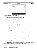
Page 10: ...er switch being in ON or OFF position At first a welcome screen will be displayed like the one below and afterwards an information about a process of gas sensors zeroing should be visible Drawing 4 Welcome screen visible straight after the analyser is starts Zeroing procedure takes 120 seconds and is necessary for measurements precision A countdown timer visible on the screen shows the time remain...

Page 11: ...pe with a probe holder Connect a gas hose to the analyser both connectors gas and electric Connect the analyser to the mains power supply if analyser is to work from the battery this step can be skipped Start the analyser with the switch on the front panel right side of the panel close to the handle Then a process of zeroing the sensors will start and after about 2 minutes the analyser is ready to...

Page 12: ...ast 90 measurements in its inner memory Analyser can display value averaged for chosen time from these stored results You can set the averaging time to one of these values 2s 6s 10s 20s 30s 60s 120s 180s Attention This operation will change the averaging time globally If the averaged results are being saved all of them will be stored with the new time set Measurement time XL it is a time of single...

Page 13: ...eters screen with the ESC key this will transfer Results screens screen 5 3 1 1 NO in NOx Pressing the change function key in setting NO in NOx on the Measurement parameters will make the screen below appear Drawing 7 NO in NOx value setting screen This value can be changed with the numeric keypad or with the arrow keys left right key will change the indicator position up down key will change the ...

Page 14: ...s differ depending on the analysers configuration M003 multiple saving measurement enrolling Number represents value of remaining savings to be done F1 ID number of fuel set change can be done from Measurements parameters screens T 2s averaging time change can be done from Measurements parameters screens If working time of the analyser is shorter than averaging time displayed value will equal the ...

Page 15: ... Print options screen Param go to Measurement parameters screen Measured gas concentrations are displayed like below CO volume concentration of a gas or ppm COm mass concentration mg m3 CO mass concentration in relation to oxygen mg m3 The same symbols are used on the printouts Results on the screen are updated every 2 seconds At any time the result is averaged for chosen time 15 ...

Page 16: ... axis displays value of the variable X horizontal axis displays time last 180 seconds of the measurement Results are presented by the curve on the graph Name of the variable its number and unit are displayed on the right side of the graph Description of function keys available on the Results screen number 4 M go to the Saving options screen change presented gas channel to the next one change prese...

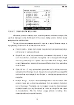
Page 17: ...ariable removes currently chosen variable on the graph from the list of available values for the graph Show all variables adds all variables to the available for the graph list Set to default sets graph into factory default settings the list of available variables will be changed to over a dozen of most important ones 5 3 3 Saving options screen GA 60 stores the measurements results as reports wit...

Page 18: ...an be changed with left right arrow keys or through the options screen available from savings option screen Measurement results will be averaged for the time of the whole time of the XL test Triple XL test 3 long measurement processes will be carried each one lasting the time of a single XL test Measurements results will be averaged for the time of the whole single XL test Results for the triple t...

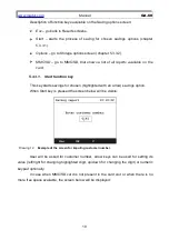
Page 19: ...Start function key This key starts savings for chosen highlighted with an arrow savings option When Start key is pressed the screen below will be visible Drawing 12 Example of the screen for imputing customer number User will be asked for customer number arrow keys can be used for setting its value left right for changing highlighted digit up down for changing the digit or numeric keypad optionall...

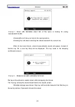
Page 20: ... screen measurements results will appear Instead of function key M a new key Stop will be displayed This key leads to the stopping confirmation screen Drawing 14 Example screen with confirmation for XL test Esc key will lead back to results screen without stopping the XL test The Yes key will stop the test and lead back to the results screen If Multiple storage was chosen Stop key will be visible ...

Page 21: ... screen will open the screen with storage options Drawing 16 Storage options screen Changing parameters can be achieved by using the arrow keys left right or by pressing the Change function key These are the available settings Storage interval this parameter concerns only the multiple storage option It describes time interval between each results savings for measurements averaged to the specified ...

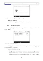
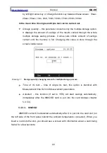
Page 22: ... value is done through the screen visible below Drawing 17 Storage quantity changing screen for multiple storage process Time of XL test time of single XL test this option is identical with Measurement time XL from Measurement parameters Autostart this function if set to YES will start savings automatically immediately after the MMC SD card is put into the card slot see chapter 5 3 3 3 5 3 3 3 MMC...

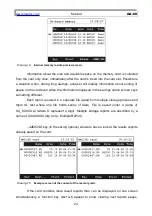
Page 23: ...MC SD card is in the card slot The analyser will try to initialize the multiple storage saving process Then user will be asked for customer number Card in the card slot blocks savings to the analysers internal memory However it is possible to move previous results from the internal memory to the memory card To do that you must get to the Internal memory screen and press MMC SD function key Please ...

Page 24: ...ething different Each report is stored in a separate file apart from multiple storage process and triple XL test where one file holds series of data File is saved under a name of XX_XXXXX rp where X represent a digit Multiple storage reports are described by a name of XXXXXXXX mrp mrp Multiple RePort MMC SD key in the saving options allows to have a look at the results reports already saved on the...

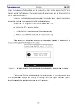
Page 25: ...line of the screen of MMC SD card 00000216 RP name of the file 15 08 04 23 31 date and time of the measurement 65530 size of the file amounts of records in the file If the card is not recognised correctly by the analyser instead of Drawing 20 a screen with request for a format will be visible Drawing 21 Example screen of the format request when card was not recognised by the device Function Key Fo...

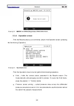
Page 26: ...n Screen From the Operation screen one can perform the following operations Hold holds the current values presented in the Results screen The measurements and averaging are still in process To leave the Hold mode press the asterisk function button Pressure sensor zeroing actual pressure value across the differential pressure connectors is set to 0 It is recommended to use this function before the ...

Page 27: ...ng the gas sensors for 3 minutes and after that time zeros the gas sensors in the same way like it is performed while starting up the device Caution Make sure that during ventilation analyser gather atmospheric air inert gas from the GAS connector Gas sensors zeroing FAST performs fast zeroing that lasts 10 seconds Caution Before using this operation the sensors must be ventilated for at least for...

Page 28: ... Screen of flow setting for soot measurements 3 Observe the flow meter set the flow value to 100 l h by regulating the pump efficiency using function keys 4 When the flow is set press the Stop function key and set the pointer at the Soot test 5 Put the clean paper filter into the hose s holder and start measurement by pressing Start function key 6 To confirm the measurement choose Yes to cancel ch...

Page 29: ...meter and if necessary regulate the pump efficiency using function keys Drawing 27 Soot measurement screen 8 When the measurement is finished read the soot level from paper filter compare it with the paper scale and enter the result into the analyser Drawing 28 Screen for entering the soot level into the analyser 29 ...

Page 30: ...memory card will be initialised Printout will contain information about the time when the results were performed fuel setting averaging time setting customer and results Optionally you can choose between 8 formats of data printing options First 4 are factory default settings and they can include only some of measurement results in the printout The remaining 4 are set for each analyser separately d...

Page 31: ...cludes values of mass concentrations of measured gases 5 3 6 Menu To get to the menu from the results screen you have to press the right arrow key or any of the numerical keys A screen visible below will be displayed Drawing 30 Menu screen A description for all options in the menu is listed below 5 3 6 1 Measurement parameters This screen is described in chapter 5 3 1 31 ...

Page 32: ...m Language changing the analysers language Contrast contrast of the screen can be set between the value of 0 and 5 Main pump setting pump s efficiency Values between 50 and 100 are possible with the interval of 5 This setting can be used only if the next setting external pump is set to NO External pump this option allows switching the main pump off and makes cooperation with external pump possible...

Page 33: ...p to 4 separate reports can be stored in this memory Description of a single line of the screen of internal memory 000121 serial number of the report Digit 1 informs that it is the first report of the set of 3 12 08 04 11 10 date and time of the measurement K0010 customer number 3min averaging time of the results In case of XL report this value indicates the time of measurement Each of the reports...

Page 34: ... 5 3 6 4 Gas conditioner Drawing 34 Gas conditioner screen This screen shows settings for the external gas conditioning unit PGD 100 that can work in cooperation with the GA 60 and function keys allow changing settings for the conditioning unit gas dryer Setting available include pump efficiency heated hose temperature and the temperature of cooling unit The column Is displays the set values read ...

Page 35: ...d hose and the cooler Not ready the dryer communicates with the analyser but it did not reach set parameters values the hose temperature and the cooler ERROR displayed when no heated hose is connected to the analyser when the hose overheats or when it cannot reach set temperature OFF the dryer is connected to the analyser but switched off NO DRYED the dryer does not communicated with the analyser ...

Page 36: ...ing date and time setting Date format setting includes to variants day month year or month day year Lower part of the Clock Calendar screen contains a month time calendar 5 3 6 6 Service Drawing 37 Service screen This screen gives access to basic functions of the analyser as well as to the more complex settings 36 ...

Page 37: ... madur services 5 3 6 6 3 IR sensors calibration Attention IR sensors calibration performed by untrained member of staff can cause loss of correct analyser s setting and in consequence make further measurement impossible Madur company strongly discourages changing settings in this menu without a proper training IR sensor calibration from the analyser is only a small correction of 1 or 2 calibratio...

Page 38: ...ge After choosing the sensor to be calibrated press the Enter function key to go to the calibration process The calibration process of the IR sensor from the analyser level is a simple transformation movement and or rotation of a factory set curve saved in the analysers internal memory The transformation is based on 2 calibration points zero gas gas value that the analyser zeroed the sensors and r...

Page 39: ... measuring at the moment called point zero Calibrate setting the second calibration point with the concentration value measured from the reference gas Remove zeroing removes the point for zero gas In this case the curve will be moved based on 2 points entered value of concentration for reference gas and factory set zero point Restore factory calibration this option restores factory settings to the...

Page 40: ... reference gas setting 5 After the reading under current results stabilises calibrate with the Calibrate option 6 Check if the current results reading equals the reference gas concentration value If not repeat calibration and this time extend time of tests for the reference gas and fresh air 5 3 6 6 4 ElChem sensors calibration Attention Electrochemical sensors calibration performed by untrained m...

Page 41: ...sors all sensors available for calibration will be visible in the sensor list and are marked with the badge The calibration screen will be displayed after the sensor is chosen and function key Enter is pressed Drawing 43 Electrochemical sensor calibration screen Electrochemical sensor calibration process is the same as in case of IR sensors The calibration curve for the electrochemical sensor is i...

Page 42: ...Warning confirmation screen for making sure that it was not accessed by mistake going forward is possible with they Yes function key a b Drawing 44 Pressure calibration a warning screen b a list of all possible IR sensors The calibration curve for pressure sensor is like in case of electrochemical sensors a straight line that can be set simply with a use of only two calibration points In the top p...

Page 43: ...setting the second calibration point pressure measurement connector should be connected to the reference pressure Restore factory calibration this option restores factory settings to the course of the straight line for the pressure sensor 5 3 6 6 6 Restore settings of the Multi module This option restores factory setting to the electrochemical NDIR and pressure sensors 5 4 Ending work with the ana...

Page 44: ...ces as the they can cause sensors destabilisation or can even lead a sensor damage Never switch off the analyser before the gas gas system is ventilated The analyser should be stored in a dry cold place to minimise sensors wear 6 2 Service In time electrochemical sensors loose their parameters so the analyser should be serviced and recalibrated regularly 7 COMPUTER SOFTWARE MadCom computer softwar...

Reviews: