20
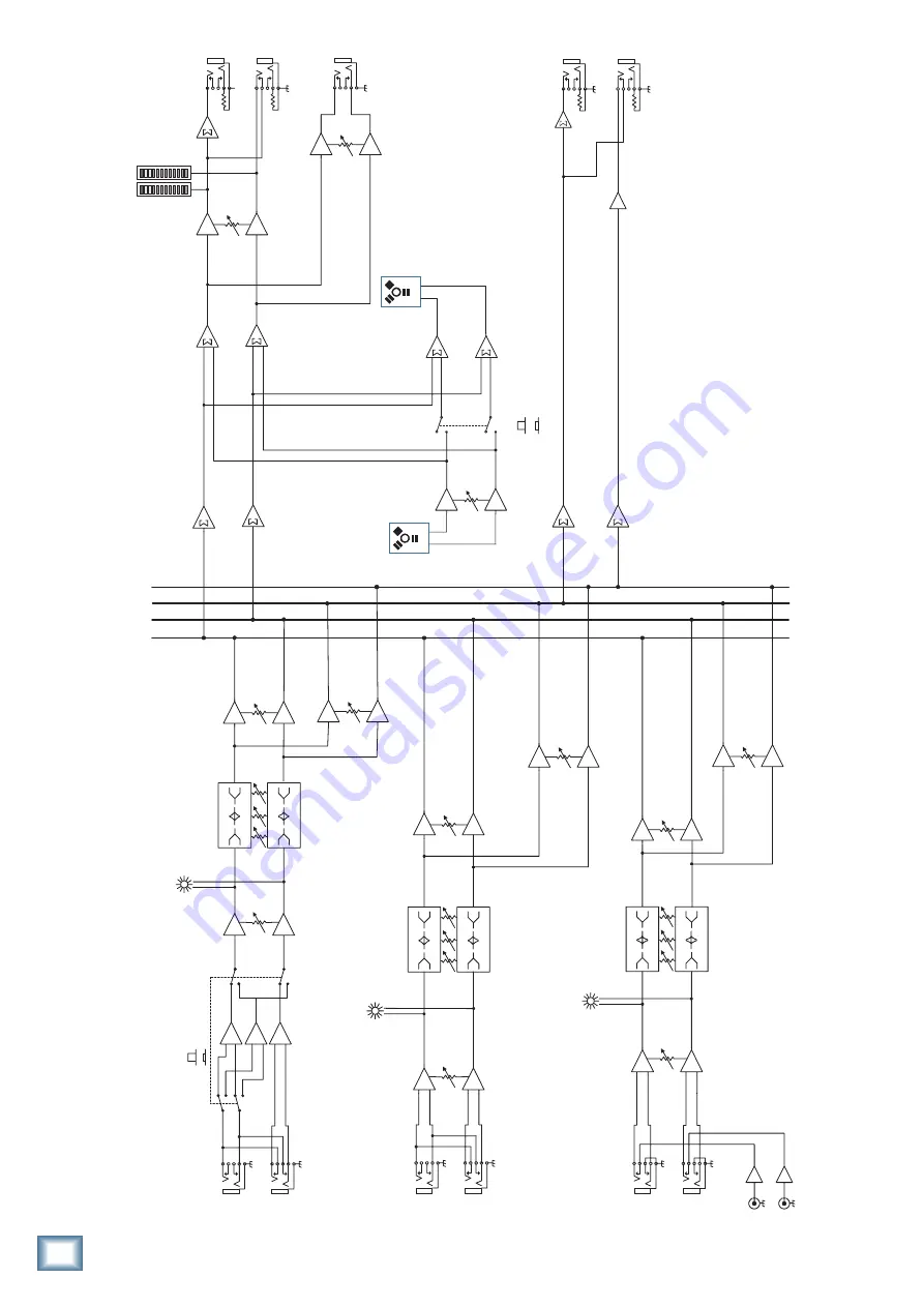
U.420 4-Channel Line Mixer
U.
4
20 4-Channel Line Mix
er
Block Diagram
L
R
Main
L
R
Main
Main
Ou
t
le
ve
l
Le
ve
l
Aux
Ou
t L
L
R
Aux L
Main
Ou
t L
Ph
on
es
le
ve
l
NOTE: Switches are shown in the default (o
ut
) po
si
tion
.
Channels
2-
3
L
R
3-Band
EQ
Ga
in
Ga
in
LO
HI
MID
LO
HI
MID
Main
Ou
t R
Aux
Ou
t R
Phon
es
Chann
el
4
Aux R
Au
x
Le
ve
l
L
R
3-Band
EQ
Ga
in
LO
HI
MI
D
LO
HI
MI
D
Au
x
L
Phon
o
R
Le
ve
l
Channel
1
L
R
3-Band
EQ
LO
HI–Z
HI
MID
LO
HI
MID
Au
x
HI-
Z
No
rm
al
FireWir
e
In
from Comp
ut
er
Fi
re
wi
re
In Le
ve
l
Firewire
Su
m
Le
ve
l Se
t
Aux
L
Aux
R
Le
ve
l Se
t
RI
AA
preamp
Ch.1-
4 to FW output
FireW
ire input
and Ch.1-4
to FW outpu
t
L
R
Main
Mi
x
Su
m
Chan
ne
l
Aux
Sum
Su
m
L
R
L
R
FireWir
e
Ou
t
to Comput
er
Ma
in
Ou
t
Le
ve
l
Le
ve
l Se
t
DA
C
AD
C
L
R


