background image

23

Owner’s Manual

Owner’

s Manual

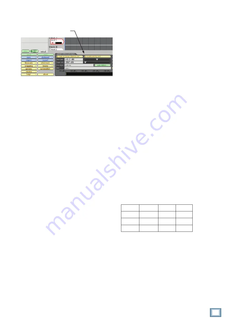
* In Tracktion, it is not necessary to mute the output 

of the track you are overdubbing on. Instead, select the 
input to the track (it will be highlighted in red) and dis-
able the end-to-end function.

You’ll hear existing tracks playing back via the 

FireWire in, and you’ll be monitoring the track you are 
recording through the U.420’s headphones or main out. 
When you play back the recording, you’ll hear the track 
you’ve just overdubbed without un-muting anything. 

Other tips

•  One drawback of using direct hardware moni-

toring (vs. through-DAW monitoring) is that 
the track you are recording will not normally 
be able to take advantage of any effects that 
the DAW’s mixer has to offer, such as a reverb 
on the vocal being recorded, or a guitar amp 
simulation on a directly attached instrument. 
One workaround for this is the following:
•  Set the latency on your DAW to as low as 

the computer can handle, and set the U.420 
software console panel to the same value 
(see page 25 for more information on the 
console).

•  Do not mute the channel on the DAW that 

is being recorded. This will allow you to 
hear a mixture of the direct hardware 
monitor, and the through-DAW signal.

•  Apply the effect of choice (reverb, amp 

emulation) to the DAW track, which you 
will hear mixed in with the direct hardware 
monitor source.

•  As long as the latency is set low enough, 

the timing difference between the direct 
and through-DAW signal should be small 
enough to not cause distraction.

A word about latency (wait-and-see)

Latency describes the amount of time it takes the 

input signal to pass through the system, and reach 
the output. When recording a guitar and monitoring 
through software, it is the amount of time it takes from 
the moment you strike your guitar string, to the moment 
you hear it in your headphones. You are used to this la-
tency being very close to zero; when you play your guitar 
through a guitar amp, you hear the signal immediately. 
So when you are recording and monitoring via software, 
you want this latency to be very low.

We would like to set the latency as low as possible, but 

the smaller it is, the harder the computer will have to 
work. If the latency is very small, the computer needs to 
work very hard to quickly transfer the audio in and out. 
It may not even be able to keep up, especially if there 
are lots of tracks, lots of automation and/or lots of plug-
ins in your work. If this happens, your audio may stop or 
“drop out.” Drop outs may also occur if you have a slower 
computer or not enough memory. 

When recording using the overdub method, it is 

important to set the U.420’s latency to it’s lowest oper-
able setting. This means going into the audio interface 
property page of your recording program and setting the 
latency property to the lowest setting the device and 
your system will accept without any drop-outs, distor-
tion or CPU overburdening. 

The buffer is an area of computer memory that your 

DAW uses to hold audio as it works. The smaller the 
buffer, the faster audio gets in and out of your com-
puter, and the lower the latency. The size of the buffer 
is measured in samples. Depending on your system, a 
low setting is typically between 64 and 256 samples. The 
more samples, the higher the latency time value. This 
time value varies by sample rate, as shown in this table.

It is generally accepted that delay or latency times of 

3.3 ms or less, are tolerable for musical timing accuracy. 

Higher latency settings are fine and even necessary 

when in live record or performance mode. The same is 
true for mix-down mode, especially when you start add-
ing lots of plug-ins. 

Samples 44.1 kHz

48 kHz

96 kHz

64 

1.5 ms

1.3 ms

0.7 ms

128 

2.9 ms

2.7 ms

1.3 ms

256

5.8 ms

5.3 ms

2.7 ms

Summary of Contents for U.420

Page 1: ...AX 1 2 3 4 U O O MAX LEVEL U O O MAX U 14 14 U 14 14 MID LOW HIGH EQ GAIN 10 KILL U 10 KILL U U U 10 KILL U 10 KILL U 10 KILL U 10 KILL 10 KILL 10 KILL 10 KILL 10 KILL 10 KILL 10 KILL LEVEL SET LEVEL...

Page 2: ...18 This apparatus does not exceed the Class A Class B whichever is applicable limits for radio noise emissions from digital apparatus as set out in the radio interference regulations of the Canadian...

Page 3: ...AMS 6 REAR PANEL FEATURES 10 1 INSTRUMENT LINE INPUT 10 2 LINE INPUTS 10 3 PHONO INPUTS 10 4 GND TERMINAL 10 5 AUX OUTPUTS 10 6 MAIN OUTS 11 7 HEADPHONES OUTPUT 11 8 DC INPUT 11 9 FIREWIRE CONNECTION...

Page 4: ...d EQ on each channel with kill position Phono preamplifier on channel 4 accepts phono level stereo signals from a turntable Instrument level input option on channel 1 Stereo aux bus allows a separate...

Page 5: ...xer If you want to listen while you work plug headphones into the phones jack on the front panel then set the phones knob up a little 1 Play something into the selected input Be sure that the volume o...

Page 6: ...r for record ing with most DAW applications like Tracktion Cubase or Sonar This is independent of the Big Knob as well Additionally there is a stereo return from the laptop that has its own mix level...

Page 7: ...ing with most DAW applications like Tracktion Cubase or Sonar Perfect for recording your set Any play back software applications like Ableton Live or Tracktor can easily be part of your performance by...

Page 8: ...output is being sent to a pair of SRM150s on mic stands for stereo stage monitoring A laptop is connected via FireWire This laptop is loaded with awesome virtual instruments like those in applications...

Page 9: ...to channel 1 DVR decks connected to channels 2 and 3 and an iPod docking station connected to channel 4 The main outputs are fed to a pair of Mackie HR studio monitors for local monitoring and the mi...

Page 10: ...e will appear equally on the left and right of the main mix This does not apply to channel 4 3 PHONOInputs Channel 4 s RCA jacks accept stereo phono level signals from turntables Check that your turnt...

Page 11: ...meters 7 HEADPHONESOutput This 1 4 TRS stereo jack is where you plug in your stereo headphones The headphone volume is controlled by the phones level control 22 It is not affected by the main level c...

Page 12: ...players keyboards drum machines and tape players You will need a DI box if connecting instrument level signals to the inputs when this switch is out 12 GAIN These knobs allow you to adjust the gain o...

Page 13: ...In the center position U low EQ has no effect The frequency range below 300 Hz represents the realm of bass drums bass guitar fat synth patches and lower down to some really serious male singers 16 AU...

Page 14: ...blink occasionally or not at all 20 FWIN This control lets you adjust the signal level of the two FireWire channels coming in from your computer rela tive to the mix of channels 1 to 4 Adjust it care...

Page 15: ...the way down before connecting headphones or making any connec tions Keep it down until you ve put on the headphones and turn it down first whenever you play a new source or instrument 23 MAINLEVEL T...

Page 16: ...y you ll know which input source is causing the problem It helps to plug all the audio equipment into the same AC circuit so they share a common ground If the annoying humming continues ask the drum m...

Page 17: ...visit www mackie com click Support and select Locate a Service Center Service for Mackie products living outside the United States can be obtained through local dealers or distributors If you do not h...

Page 18: ...Unbalanced Wiring Sleeve Shield Tip Left Ring Right 1 4 TS Phone Plugs and Jacks TS stands for Tip Sleeve the two connection points available on a mono 1 4 phone jack or plug They are used for unbalan...

Page 19: ...ed 0 0 5 dB Distortion THD N Main and aux output 20 Hz to 20 kHz 1 kHz input signal Line input at unity gain 4 dBu input signal Better than 0 008 Phono input at unity gain 30 dBu input signal Better t...

Page 20: ...O HI MID Main Out R Aux Out R Phones Channel 4 Aux R Aux Level L R 3 Band EQ Gain LO HI MID LO HI MID Aux L Phono R Level Channel 1 L R 3 Band EQ LO HI Z HI MID LO HI MID Aux HI Z Normal FireWire In f...

Page 21: ...om the mixer is converted to digi tal signals by the FireWire interface s A D converters The following table shows the outputs to your com puter from the FireWire interface Here are two examples of us...

Page 22: ...separate virtual mixer for monitoring The U 420 ALWAYS provides zero latency monitoring by design without any extra configuration Hurrah Due to the nature of its signal path the U 420 requires the use...

Page 23: ...r guitar string to the moment you hear it in your headphones You are used to this la tency being very close to zero when you play your guitar through a guitar amp you hear the signal immediately So wh...

Page 24: ...e U 420 CD ROM into your PC s CD ROM drive 3 Click Start in the task bar then click Run and click Browse Browse to your CD drive and double click _SETUP EXE Then click OK to start the installation 4 T...

Page 25: ...you are ready to use the FireWire capabili ties of your U 420 Console PConly You should adjust the sample rate and latency from within your audio software application for example in Tracktion s setti...

Page 26: ...settings for the U 420 You can also choose the U 420 as your default input or output as well as designate it to be used for the system sound output 5 You re ready to go with any Mac OS X Core Audio h...

Page 27: ...t to an authorized service center The return ground shipment is covered for those units deemed by us to be under warranty Note You must have a sales receipt from an authorized Mackie dealer for your u...

Page 28: ...Road NE Woodinville WA 98072 USA United States and Canada 800 898 3211 Europe Asia Central and South America 425 487 4333 Middle East and Africa 31 20 654 4000 Fax 425 487 4337 www mackie com E mail s...

Reviews: