background image


16 


• 

If the machine is not used for a long period, clean it carefully. Wash and dry the tub and 
the filters. Leave the door open while the machine is not in use. Turn off the water and 
disconnect the power supply. 


• 

In case of malfunctions, immediately switch off the appliance, turn off the water and 
disconnect the power supply. Call a service technician. 


IMPORTANT  


QUALIFIED PERSONNEL ONLY 


• 

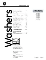
The electrical control panel features all the appliance’s components except : pump, 
heating elements, rinse-aid dispenser and solenoid valves. These components can be 
accessed by removing the lower front panel. 

N.B. : Before any technical service, disconnect the machine from the mains.  
(Fig. 5-1


Fig.  5-1 


3.3  IF THE DISHWASHER IS NOT USED FOR LONG PERIODS 

4.  IN CASE OF MALFUNCTIONS 

5. SERVICEABILITY  

Summary of Contents for MS 900E

Page 1: ...REV 00 15 07 05 COD 6000276 00 MS 900E 73 23 93 68 89 336 INSTRUCTIONS BOOKLET FOR INSTALLATION MAINTENANCE OPERATION FOR DISH WASHERS...

Page 2: ...ngerous 3 Before switching the equipment on make sure that the model plate data conforms to that of the electrical and water distribution network 4 Installation should be carried out by qualified pers...

Page 3: ...OWER SUPPLY 8 2 1 1 GROUND 8 2 2 CONNECTION TO WATER SUPPLY 9 2 3 WATER DRAIN 10 3 INSTRUCTIONS FOR USE 12 3 1 START UP 12 3 1 1 WASHING PROGRAMMES 14 3 1 2 DETERGENT AND RINSE AID 14 3 2 CLEANING 15...

Page 4: ...l of the machine It contains all the neccessary data to install the appliance Fig 1 1 MS 900E Overall dimensions mm 650 x 710 x 1460 Basket size mm 500 x 500 Washing power P h 900 Tank capacity lt 34...

Page 5: ...5 Fig 1 2 A Water drain 30 B Connection to water mains 3 4 G 1 1 SCHEMATIC VIEW...

Page 6: ...6 1 2 ELECTRICAL DIAGRAM...

Page 7: ...lenoid valve IG Main switch M Terminal board MP Door microswitch PL Washing pump PS optional Drainage pump PV Tank pressureswitch R R1 Relays R2 optional Relays RB Boiler heating element RV Tank heati...

Page 8: ...n to power supply is on the back side of the appliance The power cable G must have a rating of at least H05VVF and each wire must have a section of 2 5 mm N B In accordance with international standard...

Page 9: ...es Pressure must be measured at the solenoid valve inlet see fig 2 4 The water pipes must have an internal diameter of at least 16 18 mm see fig 2 5 Connect the appliance water supply pipe to a cut ou...

Page 10: ...ers good for dish washers very good for dish washers Fig 2 5 Connect the drain hose of the appliance to the outlet D fitting a siphon between the hose and the outlet Alternatively place the appliance...

Page 11: ...11 Fig 2 6 Fig 2 7...

Page 12: ...ON switch 1 which will cause the warning light A to illuminate indicating that the machine is live When the door is closed the appliance fills with water When it is full the tub and boiler heating ele...

Page 13: ...13 RECOMMENDED TEMPERATURE boiler 90 C tub 60 C Fig 3 1 Fig 3 2...

Page 14: ...iance is off Fig 3 1 3 3 Add detergent every 5 6 wash cycles N B It is recommended ta start the wash cycle when both litgh of the heating elements boiler C and tank B are off as indicated at point 3 1...

Page 15: ...arts in running water and replace them with care WARNING Before removing the filters S clean residual foreign matter from the bottom of the tub N B Turn off the master switch A before cleaning the out...

Page 16: ...ter and disconnect the power supply Call a service technician IMPORTANT QUALIFIED PERSONNEL ONLY The electrical control panel features all the appliance s components except pump heating elements rinse...

Page 17: ...17...

Page 18: ...18...

Page 19: ...19...

Page 20: ......

Page 21: ......

Page 22: ...20 Unit 7 Church Park Lowfield Heath Crawley West Sussex RH11 0PW Sales 01293 571199 Fax 01293 571133 Email sales mpswholesale co uk www mpswholesale co uk...

Reviews: