Publication: MAN3002G
MAC Equipment, Inc.
8
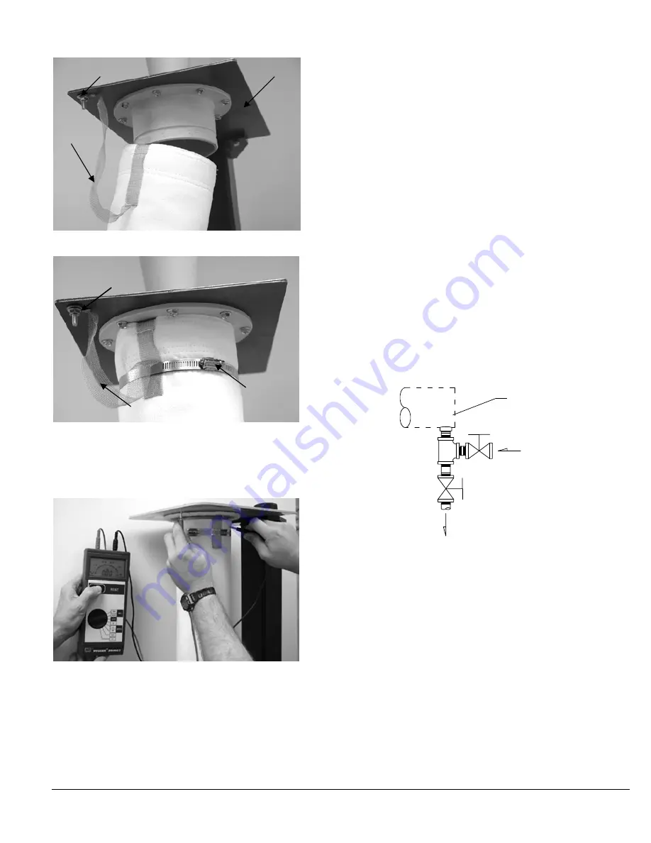
Section B: Verification of Proper Grounding
Proper installation must be confirmed by testing to verify 1x10
6
(1
megohm) maximum resistance at 500 volts between cage and tubesheet
(cell plate).
Bottom load collector: testing resistance between cage and
tubesheet
In addition to the proper installation and grounding of bags and cages,
the end user should select an appropriate filter media for use in bags.
Refer to the National Fire Protection Association (NFPA)
“
Recommended
Practice on Static Electricity,
”
NFPA 77
-2000 edition for more information
(www.nfpa.org).
Compressed Air Requirements
Compressed Air
For most applications, compressed air at 80-100 PSIG at the filter header
is adequate for proper cleaning of the filter bags. Pressures between
100-120 PSIG may be appropriate for some critical applications.
Operations at pressures above 100 PSIG should be reviewed with MAC
Equipment Inc. for approval and recommendations. Compressed air
pressures below 80 PSIG require special considerations in the design
and sizing of the filter and also should be reviewed with MAC.
Compressed Air Quality
Trouble free, maintenance free operation is largely dependent on
providing clean, dry, oil free compressed air. The importance of clean,
dry, oil free compressed air cannot be over emphasized. Dirt, rust and
scale can prevent diaphragm valves from operating properly. Moisture
can cause valves to freeze in cold weather. Moisture and oil can cause
deterioration of the valve diaphragms, and if the interior of the filter bags
become coated with moisture and/ or oil, eventual plugging of the filter
media can occur.
The degree to which a compressed air system must be provided with
safeguards to eliminate dirt, scale, moisture, and oil, will depend on the
type of compressor, aftercoolers, receivers, and accessory equipment
chosen or available, the piping material used, the piping layout between
the compressor and the dust collector compressed air header, the lowest
temperature to which the piping will be exposed, and the type of process
and process conditions encountered.
Clean Compressed Air
1.
A simple drip leg installed at the point where the air line connects to
the compressed air header is usually sufficient to trap small amounts
of dirt, rust, and scale, and to serve as a low point to drain moisture
when a shutoff valve is installed.
AIR HEADER
AIR SUPPLY
TO DRAIN
Figure 4-9 Drip Leg (supplied by customer)
2.
An in-line filter or a centrifugal separator is required where large
amounts of dirt, rust and scale are present, and especially where a
possible shut down of the system is critical.
Dry Compressed Air
Liquid Moisture Traps:
1.
An automatic moisture drain should be installed on the compressed
air receiver. Automatic drains are available in a variety of float
operated types, piston types and pilot types.
2.
Small amounts of liquid moisture can be handled with in-line air
filters with automatic drains.
3.
Large amounts of liquid moisture require a centrifugal separator
followed by a chemical dryer (consumable desiccant requiring
replacement) to filter out the water droplet carry over. The dew point
is dependent on the temperature of the cooling water used at the
after cooler.
Tubesheet
Plastic bag cup
Terminal attached to grounding lug
Grounding strap
Clamp
Grounding strap
Terminal
Summary of Contents for AVR
Page 2: ......
Page 15: ...Publication MAN3002G MAC Equipment Inc 12 ...
Page 16: ...Publication MAN3002G MAC Equipment Inc 13 ...
Page 17: ...Publication MAN3002G MAC Equipment Inc 14 ...
Page 18: ...Publication MAN3002G MAC Equipment Inc 15 ...
Page 19: ...Publication MAN3002G MAC Equipment Inc 16 ...
Page 20: ...Publication MAN3002G MAC Equipment Inc 17 ...
Page 24: ......
Page 25: ......


