background image

Fig. 20

Fig. 21

67

70

23

68

Adjusting the bevel stops

This saw has positive stops that will quickly position the saw blade at 90° or 45°
to the working table.
The angle settings of the saw have been set at the factory and, unless damaged
in shipping, should not require setting during assembly. After extensive use, it may
need to be checked.
Make adjustments only if necessary.
> Unplug the saw.
> Remove the blade guard.
> Raise  the  blade  to  the  maximum  height  by  turning  the  high  adjusting
   handle counterclockwise.
> Using a square [67], set the blade [23] to exactly 0°. (Fig. 20)

> If the blade stops bevelling before it gets to 90°, using the 4mm hex key (not
   supplied) to loosen the 90° stop set screw [68] (located at the left of the bevel
   track on the front), and then adjust it to 90°.
> With the blade set at 90°, slowly turn the 90° stop set screw [68] until you feel
   resistance. Bevel the blade away from 90° a little, and then back to the stop.
> Re-measure the angle and repeat the stop adjustment as necessary until the
   blade stops at 90°.

ADJUSTMENT

In

 more 

detail…


In

 more 

detail…


Product functions

MSTS1500-A 

by 

MacAllister

45

EN

Summary of Contents for 3663602467571

Page 1: ...Original Instructions_MNL_MSTS1500 A_GB_V02_190910 MSTS1500 A 1500W Table Saw EAN 3663602467571 WARNING Read the instructions before using the product EN ...

Page 2: ...ing and disposal Trouble shooting Guarantee EC declaration of conformity 34 02 03 05 19 Getting started Your product Technical and legal information Before you start These instructions are for your safety Please read through them thoroughly before use and retain them for future reference Let s get started EN ...

Page 3: ...MSTS1500 A by MacAllister Getting started 03 Your product Your product 17 16 18 19 20 21 22 26 27 24 23 25 28 13 4 5 7 6 15 14 1 2 3 8 9 11 10 12 EN ...

Page 4: ... always be used if the distance between the rip fence and saw blade is less than 12 cm 1 Dust extraction adapter 2 Right extension table 3 Riving knife 4 Rubber foot 5 Stand 6 Height adjusting handle 7 On Off switch 8 Bevel adjusting handwheel 9 Overload reset switch 10 Bevel locking handle 11 Front rail 12 Mitre gauge 13 Left extension table 14 Blade guard 15 Dust extraction hose 16 Rear extensio...

Page 5: ...uld only be connected to a supply having a system impedance lower than 0 2496ohm In case of need you may contact your local supply authority for further information Important note Remove the mains plug from socket before carrying out any adjustment or servicing Ensure your mains supply voltage is the same as your tool rating plate voltage The following information applies to professional users onl...

Page 6: ...tool e g a block cutter instead of angle grinder 3 Using a different method of work altogether e g using a nail gun to direct fasten cable trays instead of drilling holes first Please always work with approved safety equipment such as those dust masks that specially designed to filter out microscopic particles and use the dust extraction facility at all time For more information please see the HSE...

Page 7: ...ials being cut or drilled The tool being in good condition and well maintained The use the correct accessory for the tool and ensuring it is sharp and in good condition The tightness of the grip on the handles And the tool is being used as intended by its design and these instructions While working with this power tool hand arm vibrations occur Adopt the correct working practices in order to reduc...

Page 8: ... scheme to help identity any vibration related diseases at an early stage prevent disease progression and help employees stay in work Wear hearing protection Wear eye protection Wear respiratory protection For woodwork only Caution Warning Pay attention to your hands and other parts of your body when working with and on the saw Read the instruction manual Class II construction Unlock to loosen Loc...

Page 9: ...you to lose control 2 Electrical safety a Power tool plugs must match the outlet Never modify the plug in any way Do not use any adapter plugs with earthed grounded power tools Unmodified plugs and matching outlets will reduce risk of electric shock b Avoid body contact with earthed or grounded surfaces such as pipes radiators ranges and refrigerators There is an increased risk of electric shock i...

Page 10: ...otection Protective equipment such as dust mask non skid safety shoes hard hat or hearing protection used for appropriate conditions will reduce personal injuries c Prevent unintentional starting Ensure the switch is in the off position before connecting to power source and or battery pack picking up or carrying the tool Carrying power tools with your finger on the switch or energising power tools...

Page 11: ...s and any other condition that may affect the power tool s operation If damaged have the power tool repaired before use Many accidents are caused by poorly maintained power tools f Keep cutting tools sharp and clean Properly maintained cutting tools with sharp cutting edges are less likely to bind and are easier to control g Use the power tool accessories tool bits etc in accordance with these ins...

Page 12: ...saw blade diameter must match the appropriate riving knife the body of the saw blade must be thinner than the riving knife and the tooth width has to be greater than the thickness of the riving knife 2 Safety instructions for sawing procedures a DANGER Keep fingers and hands away from cutting area and the blade A moment of inattention while operating power tools or slipping might cause your hand t...

Page 13: ...a uniform speed Do not bend or twist the workpiece If the saw blade jams immediately switch off the power tool pull the mains plug and clear the jam If the workpiece causes the jamming of the saw blade this could lead to kickback or stalling of the motor k Do not remove piece of cut off material while the saw is running The material may become trapped between the saw blade and fence or in the guar...

Page 14: ...sag under their own weight Supports must be placed under the panel on both sides near the line of cut and near the edge of the panel h Use extra caution when cutting a workpiece that is twisted knotted warped or does not have a straight edge to guide it with a mitre gauge or along the fence rail A warped knotted or twisted workpiece is unstable and causes misalignment of the kerf with the saw blad...

Page 15: ...1 8 mm match the riving knife with thickness of 2 mm i Always use only a saw blade diameter in accordance with the markings on the saw Use only saw blades for which the maximum possible speed is not less than the maximum spindle speed of the product j Never use damaged or incorrect saw blade mounting means such as flanges saw blade washers bolts or nuts These mounting means were specially designed...

Page 16: ...rigerators when operating this machine Do not use the power cable for any purpose it is not intended for Risks of personal injury and crushing by moving parts Do not operate the machine without installed guards Always keep sufficient distance to the saw blade Use suitable feeding aids if necessary Keep sufficient distance to driven components when operating this machine Wait for the saw blade to c...

Page 17: ...drawn in by rotating components no neckties no gloves no loose fitting clothes contain long hair with hairnet Never attempt to cut any workpieces which contain ropes strings cords cables or wires or to which any of the above are attached Hazard generated by insufficient personal protection gear Wear hearing protection Wear safety glasses Wear dust mask Wear suitable work clothes When working outdo...

Page 18: ...g workpieces or workpiece parts Technical and legal information MSTS1500 A by MacAllister 18 Getting started EN If blockage occurs Switch machine off Unplug mains cable Wear gloves Clear the blockage using a suitable tool ...

Page 19: ...and cut off wheels of any type is forbidden The tool is not suitable for commercial or industrial use Any other type of use is inappropriate Improper use or modifications to the tool or the use of components that are not tested and approved by the manufacturer may result in unforeseen damage Any use that deviates from its intended use and is not included in these instructions is considered unautho...

Page 20: ...ve all the accessories and tools needed for assembly and operation This also includes suitable personal protective equipment The following items are included with your table saw Left right extension table 13 2 x 02 Dust extraction adapter 1 x 01 Dust extraction hose 15 x 01 Front rail 11 x 01 Riving knife 3 x 01 Rear extension table 16 x 01 Hose hold 18 x 01 Rip fence 19 x 01 Knurled screw 48 x 02...

Page 21: ...m leg bracket 35 x 02 Rubber foot 4 x 04 Screws M6 x 12 38 x 16 Hex bolts M6 x 25 39 x 04 Flat washer 6 29 x 20 Spring washer 6 30 x 16 Hex nuts M6 31 x 20 Flat washer 6 29 x 15 Spring washer 6 30 x 13 Hex nuts M6 31 x 7 Hex bolts M6 x 16 32 x 13 Before you start MSTS1500 A by MacAllister Getting started 21 EN For stand ...

Page 22: ...le the left right extension tables Place cardboard or an old blanket on floor in order to protect the surface of the working table Carefully remove the table saw assembly from the carton Place the table saw assembly upside down on the protective material Unlock the bevel locking handle 10 anti clockwise turn the bevel adjusting handwheel 8 anti clockwise to tilt the motor and remove the polyfoam 4...

Page 23: ... 6 30 and hex bolts M6 x 16 32 Attached the left right extension tables 13 2 to the working table 24 with flat washers 6 29 spring washers 6 30 and hex bolts M6 x 16 32 Fig 1b 1c Attached the hose hold 18 to the right extension table 2 with flat washers 6 29 spring washers 6 30 hex bolts M6 x 16 32 and hex nuts M6 31 Fig 1c Before you start MSTS1500 A by MacAllister Getting started 23 EN NOTE Only...

Page 24: ...ocking handle bevel adjusting handwheel and height adjusting handle Loosen the tri wing knob 44 and pull large square washer 45 away from the side of the machine NOTE that DO NOT remove the tri wing knob 44 and large square washer 45 Insert the riving knife 3 to the left of the tri wing knob and both washers see Fig 3b Then push the riving knife down when you hear a click the pin 46 is locked into...

Page 25: ... then put the flat washers 6 29 spring washers 6 30 and loosely tighten on the hex nuts M6 31 as shown in the Fig 4b Reinstall the table insert 17 Before you start MSTS1500 A by MacAllister Getting started 25 EN NOTE The riving kinfe must be aligned with saw blade after finished and the distance between the outside edge of the saw blade and the riving knife must be three to eight millimetres If no...

Page 26: ...the rip fence locking handle 22 on the rip fence 19 with the flat washers 49 and knurled screws 48 Rip fence locking handle 22 can be mounted on left or right of the rip fence 19 as shown in Fig 4c When cutting a slim workpiece attach rip fence locking handle to the rip fence as shown in Fig 4d Before you start MSTS1500 A by MacAllister Getting started EN Fig 4c Fig 4d ...

Page 27: ... push down the rip fence locking handle 22 in order to lock the rip fence in position Carefully offer the rip fence 19 into the channel of the front rail 11 and push the rip fence 19 completely to the saw blade 23 and hold firmly Move the front rail 11 in such a way that the red line marking 50 on the guide pointer 51 is in the zero position on the scale Before you start MSTS1500 A by MacAllister ...

Page 28: ... the riving kinfe 3 to lock the blade guard 14 in place Ensure the pin 55 is located at inner side of the blade guard Ensure the blade guard rests on the working table but will lift when a work piece is pushed into the working table WARNING Risk of injury The saw blade guard 14 must be in position at all times to prevent contact with the saw blade It should lift up and onto the work piece when the...

Page 29: ...ws M6 x 12 38 flat washers 6 29 spring washers 6 30 and hex nuts M6 31 Only hand tighten the hex nuts for the time being Important There are two different sizes of parts 33 34 35 36 these must be assembled opposite each other For example part 33 must be above part 35 Make sure that that the locking pins a on the stand legs must secure in the holes b on leg brackets Tighten all bolted connections P...

Page 30: ...of the table saw positioned on the long side Insert four hex bolts M6 x 25 39 along with flat washers 6 29 into the aligned holes Tighten all four hex nuts M6 31 and hex bolts 39 30 Before you start MSTS1500 A by MacAllister Getting started EN Fig 7 36 37 35 35 33 36 33 34 34 4 a b 31 30 29 38 31 30 29 38 NOTE Do not over tighten the bolts that hold the saw to the stand Doing so will damage the sa...

Page 31: ... workbench and align the mounting holes of the table saw with the drilled holes in the workbench Firmly screw the table saw to the bench surface Carefully check the workbench after mounting to make sure that no movement can occur during use If any tipping sliding or walking is noted secure the workbench to the floor before operating Fig 8 39 29 31 To attach the dust extraction adapter and dust ext...

Page 32: ... 58 61 1 62 59 18 15 15 60 1 To prevent sawdust buildup for best result attach a vacuum hose not included to the hole C 62 of the dust extraction adapter 1 See Fig 9c DO NOT operate the saw with hose in place unless the vacuum is turned on 32 Before you start MSTS1500 A by MacAllister Getting started EN Warning Dust extraction adapter must be fitted and the table saw must regularly check for dust ...

Page 33: ... the bevel locking handle is locked Warning Risk of injury In case of malfunctions press the red 0 Button on the On Off switch 7 and pull out the mains plug Warning Risk of injury The table saw must only be put into operation if no faults are found If a part is defective it must absolutely be replaced before the next use Connection to the electrical supply Before switching on make sure that the vo...

Page 34: ...34 MSTS1500 A by MacAllister In more detail EN In more detail 35 47 52 53 55 56 Product functions Care and maintenance Recycling and disposal Trouble shooting Guarantee EC declaration of conformity ...

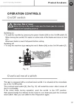
Page 35: ... on the On Off switch 7 Overload reset switch This saw is equipped with a overload reset switch It is situated at the immediate top of the On Off switch The overload reset switch 9 See Fig 10 will restart the motor after it shuts off due to overloading If the motor stops during operation push the switch to the OFF position Wait approximately five minutes for the motor to cool down and push the ove...

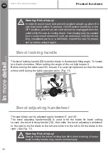
Page 36: ...heel to the right to tilt the blade to the left and slide it to the left to tilt the blade to the right See Fig 11 8 10 6 36 Product functions MSTS1500 A by MacAllister In more detail EN Warning Risk of injury In order to avoid injury and prevent accidental start up when the overload reset switch is pushed On Off switch should be in the OFF position and the power cord should be unplugged from the ...

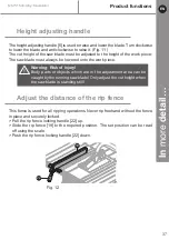
Page 37: ...must always be lowered onto the work piece Adjust the distance of the rip fence This fence is used for all ripping operations Never rip freehand without the fence in place and securely locked Pull the rip fence locking handle 22 up Slide the rip fence 19 to the required position The set position can be read off using the scale Push the rip fence locking handle 22 down Warning Risk of injury Body p...

Page 38: ... an uneven end could slip off or push the work piece away from the fence Adjust the angle of the mitre gauge The mitre gauge is locked in the desired position for crosscutting or mitring by tightening the locking handle 65 Always lock it securely when in use The mitre gauge can be adjusted by a maximum of 60 for mitre cuts Loosen the mitre gauge locking handle 65 By turning the parallel profile 66...

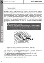
Page 39: ... injury Before using the table saw polish the tabletop with an automotive polishing wax in order to keep it clean and to make it easier to slide the work piece There are two basic types of table saw cuts rip cutting and cross cutting Rip cutting refers to cutting along the length of the grain and the work piece Cross cutting refers to either cutting across the width or across the grain of the work...

Page 40: ... speed Do not stand directly in line with the saw blade s path Instead stand on the side where the cut is being made Slowly feed the work piece into the blade by pushing forward on the section of 40 Product functions MSTS1500 A by MacAllister In more detail EN Warning Risk of injury If the distance between the rip fence and saw blade is less than 12 cm the push stick 25 must be used Warning Risk o...

Page 41: ... to reach for the push stick When both thumbs touch the front edge of the table complete the cut using a push stick Always use the push stick when performing ripping operations Continue to push the work piece with the push stick until it passes the blade guard and clears the rear of the table Do not pull the work piece backward while the blade is turning Turn the switch OFF and unplug the power co...

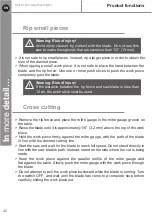
Page 42: ...de Do not attempt to pull the work piece backward while the blade is turning Turn the switch OFF and wait until the blade has come to a complete stop before carefully sliding the work piece out Rip small pieces It is not safe to rip small pieces Instead rip a larger piece in order to obtain the size of the desired piece When ripping a small work piece it is not safe to place the hand between the b...

Page 43: ...sired bevel angle Make sure the bevel locking handle is locked firmly Follow the same instruction of Cross cutting Fig 16 Fig 17 In more detail In more detail Product functions MSTS1500 A by MacAllister 43 EN Warning Risk of injury In order to avoid instability always place the larger surface of the work piece on the table when cross cutting and or bevel cross cutting ...

Page 44: ...dle is locked firmly Adjust the mitre gauge to the desired mitre angle Make sure the mitre gauge locking handle is locked firmly Follow the same instruction of Cross cutting Mitre cross cutting Mitre cross cutting is the same as cross cutting except that the mitre gauge is locked at an angle other than 90 Adjust the mitre gauge to the desired mitre angle Make sure the mitre gauge locking handle is...

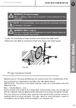
Page 45: ...t by turning the high adjusting handle counterclockwise Using a square 67 set the blade 23 to exactly 0 Fig 20 If the blade stops bevelling before it gets to 90 using the 4mm hex key not supplied to loosen the 90 stop set screw 68 located at the left of the bevel track on the front and then adjust it to 90 With the blade set at 90 slowly turn the 90 stop set screw 68 until you feel resistance Beve...

Page 46: ...on either side of the saw specifically designed for the saw s accessories rip fence 19 mitre gauge 12 push stick 25 blade wrenches 26 When not in use turn off power switch disconnect it from power supply and store accessories securely Set the 45 stop in the same way with a triangle square 69 The set screw 70 for the 45 stop is located at the right of the bevel track on the front ...

Page 47: ... Care and maintenance MSTS1500 A by MacAllister 47 EN WARNING Always switch the product off disconnect it from the power supply and let the product cool down before performing inspection maintenance and cleaning work General cleaning Keep the ventilation slots of the machine clean to prevent overheating of the engine Regularly clean the machine housing with a soft cloth preferably after each use K...

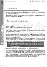
Page 48: ...d to the front rail side of the machine Remove arbor nut 72 outer blade flange 71 and saw blade 23 Place one new blade 23 on arbor shaft 73 Make sure saw blade teeth point down at the front rail side of saw table Place outer flange 71 and arbor nut 72 on arbor shaft and verify that large flat surface of the outer flange faces the saw blade and the saw blade 2 is firmly seated aganist the inner fla...

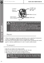
Page 49: ... wires in the mains lead are coloured in accordance with the following code Blue Neutral Brown Live As the colours of the wire in the mains lead of this product may not correspond with the coloured marking identifying the terminals in your plug proceed as follows The wire which is coloured blue must be connected to the terminal which is marked with N or coloured black The wire which is coloured br...

Page 50: ... help of another person When shipping use the original packaging if possible 10 AMP fuse approved to BS 1362 Brown L Live Cable grip Outer sleeve firmly clamped Connect Blue to N Neutral Warning Never connect live or neutral wires to the earth terminal of the plug which is marked with E Only fit an approved 13 Amp BS 1363 or BS 1363 A plug and the correctly rate fuse If in doubt consult a qualifie...

Page 51: ...n a place that is inaccessible to children Store the product operating instructions and where necessary the accessories in the original packaging In this way you will always have all the information and parts ready to hand Warning Risk of injury Store the product so that it cannot be switched on by unauthorized persons Ensure that nobody can injure themselves on the product while it is stationary ...

Page 52: ... and disposal MSTS1500 A by MacAllister In more detail EN Waste electrical products should not be disposed of with household waste Please recycle where facilities exist Check with your Local Authority or local store for recycling advice ...

Page 53: ...age relay triggered by temporary loss of power 3 Motor overheated 1 Check cable plug socket and fuse 2 Switch device on again 3 Eliminate cause of the overheating let cool down for a few minutes then switch on again Blade makes poor cuts 1 Blade is dull or dirty 2 Blade is the wrong type for cut being made 3 Blade is mounted backwards 1 Clean sharpen or replace the blade 2 Replace with the proper ...

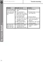
Page 54: ...riving knife is not being used 3 The blade is dull 4 The work piece has not been kept in its place until after sawing 5 Mitre gauge locking handle is loosen 1 Use the fence 2 Replace blade or mount the riving knife 3 Replace blade 4 Keep the work piece in place until finsh the sawing 5 Tighten the mitre gauge locking handle Saw does not make accurate 90 or 45 cuts 1 Positive stops inside the cabin...

Page 55: ...defects and damage caused by or resulting from Normal wear and tear Overload misuse or neglect Repairs attempted by anyone other than an authorised agent Cosmetic damage Damage caused by foreign objects substances or accidents Accidental damage or modification Failure to follow manufacturer s guidelines Loss of use of the goods This guarantee is limited to parts recognised as defective It does not...

Page 56: ... TÜV SÜD Product Service GmbH Ridlerstraße 65 D 80339 München Germany The EMC Directive 2014 30 EU 2011 65 EU EU 2015 863 Restrictions of the Use of Certain Hazardous Substances in Electrical and Electronic Equipment 2012 19 EU Waste Electrical and Electronic Equipment WEEE Regulation EC No 1907 2006 concerning the Registration Evaluation Authorization and Restriction of Chemicals REACH Standards ...

Page 57: ......

Page 58: ......

Page 59: ......

Page 60: ...er International Products Limited 3 Sheldon Square London W2 6PX United Kingdom EU Manufacturer Kingfisher International Products B V Rapenburgerstraat 175E 1011 VM Amsterdam The Netherlands www diy com www screwfix com To view instruction manuals online visit www kingfisher com products EN ...

Reviews: