background image

- 62 -


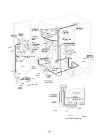
HERRAMIENTA LOKRING


CONECTOR


Bronce


PROTECTOR DE CALOR


SOLDADOR


There are two approved methods to change the evaporator. The 
Lokring  method  does  not  require  welding,  since  it  uses  tight 
mechanical  connections.  The  heat  shield  uses  the  traditional 
soldering  method,  but  gives  protection  to  the  upper  liner  while 
welding the evaporator connections in the freezer compartment. 


Always add a new drying filter when repairing the sealed system. 
Follow each step of the instructions included with the evaporator 
replacement. 

.


LOKRING METHOD 


Lokring is a method to install the evaporator in the freezer 
without  using  a  torch.  It  uses  a  mechanical  connection 
instead  of  a  soldered  connection.  Apply  a  few  drops  of 
LokPrep  (a  special  cleaning  solution  and  seal)  to  the 
terminals  of  the  pipe  you  wish  to  join.  The  Lokring  tool 
compresses the  connector  to  ensure  a tight  mechanical 
connection. The parts shown on the right are required to 
use the Lokring replacement method. 
 
For additional information on how to use the Lokring, call 
1-800-848-7722  &  order  publication  #  31-9067  (Lokring 
Repair  Procedures  Manual)  and  Publication  #  31-9066 
(VHS Video Cassette Lokring Repair Procedures) 


HEAT PROTECTOR METHOD 


The heat protection kit is used to prevent damage to the 
refrigerator  liner  when  soldering  the  evaporator  in  the 
sealed system. See the instructions included in the heat 
protection kit. The kit comes with enough heat absorbing 
paste, soldering iron and adhesive to finish four repairs. 


  Ref No.      Pieza Número       Descripción 

228           WR85X10022        Conjunto Lado Bajo 

PASTA 


Summary of Contents for GSS21 Series

Page 1: ...Training services to Mabe Consumer home Service Manual MODEL SERIES PSS and GSS 21 23 25 27 and 29 cubic feet PUB 31 9072 SP 01 0 ...

Page 2: ...ct power before servicing this product If electric power for purposes of diagnosis or test is required disconnect power immediately after making the necessary check ups RECONNECT ALL DEVICES TO LAND If you wire them screws belts fasteners or nuts the grounding used to complete a pass to earth are removed for service should be returned to his position original and adjusted properly Entrenamiento de...

Page 3: ...n Specifications Nomenclature Operation characteristics General views of localization Mechanical disassembly Diagnostics Views of localization of components and connector Diagrams Catalogs illustrated parts 2 3 4 5 6 13 15 29 52 59 60 ...

Page 4: ...rature control point type and have settings of 0 9 with 9 being the coldest possible temperature The new NON CLEAN condenser is repairable from the back and is designed to prevent the customer from having to clean the condenser in conditional normal use The sealed operation system and the compressor are working in the same way as the previous models with some minor changes The collateral models Pr...

Page 5: ...AND PACKAGING MATERIAL FROM INSIDE REFRIGERATOR DO NOT REMOVE THE SERIAL PLATE REMOVE THE PROTECTIVE FILM ON THE TEMPERATURE CONTROL PANEL IMPORTANT PLEASE READ CAREFULLY FOR PERSONAL SAFETY THIS APPLIANCE MUST BE ADEQUATELY GROUNDED The power cord of this appliance is equipped with a three prong grounded connector that fits a three pronged grounded standard receiver to minimize the risk of an ele...

Page 6: ...rly tightened IMPORTANT SAFETY NOTICE This information is intended to be used by people who have an adequate background in electrical electronic and mechanical experience Any attempt to repair an appliance can result in personal injury or property damage The manufacturer or seller cannot be responsible for the interpretation of this information nor can it assume any responsibility in relation to i...

Page 7: ...EGIONAL PROF ENERGY S ESTANDARD T TROPICAL G GLOBAL BRAND PRODUCT G GE H HOTPOINT P PROFILE GE E ETERNA GE R RCA S SELECT GE ICE MACHINE EXTERIOR B Not ready for dispenser ice maker D Ice cubes Water E Ice cubes and chopped Water F Filter ice cubes and chopped 6 months G Filter ice cubes and chopped 1 year i Filter Indicator C CW online EXTERIOR COLOR WW White White AA Almond Almond BB Black Black...

Page 8: ...Adaptive Defrosting 8 Pre Cooling Operation Adaptive Defrosting Operation Heater Defrosting Adaptive Disconnect 8 8 Rest Period Adaptive Defrosting 8 Post Rest Adaptive Defrosting 8 Liner Protection Mode 8 Electronic Ice Machine 9 Dispenser functions 9 Fast Ice 9 Door Alarm Dispenser Light 9 9 Closing the Dispenser 9 Filters 10 Hinge and Door Closing System 10 Air Flow Cabinet Interior 10 Condense...

Page 9: ...board will only respond to 8 degrees of temperature change per minute as determined by the change of resistance of thesensor 7 Abnormal Operation Characteristics Incorrect Operation Cooler fan on and evaporator fan off Evaporator fan on cooler fan and compressor off and damper closed Quick changes in fan speed the fan takes at least 1 minute to change speeds The compressor running without the cond...

Page 10: ...denser fan and evaporator fan they stay off Frost melting that remains of the evaporator will continue to fall and drain to that the evaporator to be completely clean of any humidity before the cooling operation After 5 minutes of resting period the unit enters a post break Post Rest Adaptive Defrosting The post rest period is designed to cool the evaporator before circulating the air inside the r...

Page 11: ... panel The function will be restored in the case of lack of energy Door alarm The DOOR ALARM key is used to turn on and off the alarm detail of the door If the detail is on the DOOR ALARM LED will flash when the door is opened If the door opens for more than 2 minutes the door alarm will sound The alarm can be stopped by pressing the DOOR ALARM key or closing the door If the DOOR ALARM key is push...

Page 12: ... loaded spring arm located in the lower part of the cabinet for each door The arm stops the door when it is partially open and automatically closes the door when it is almost closed IMPORTANT The refrigerator rollers must be properly adjusted for proper door closure When the wheels are adjusted correctly the door should close easily when it opens approximately 45 degrees half way Air Flow Cabinet ...

Page 13: ...ne end of the jelly roll condenser and a solid plate is located at the other end Air is drawn through the outside diameter of the condenser and pulled out by the condenser fan The condenser is located in the compartment of the machine that can be accessed through the back of the unit in the background GEA00911 ...

Page 14: ...PRESOR Y DESCONGEL SALIDAS SELECC MODELO ENTRADAS THERMISTO R ENTRADAS CODIFICADOR SERPENTINES AMORT COMMUNICACION ENTRADA SALIDA SALIDAS VENTILADOR DEPARTURES DEFROST PRE COOLI COOLING 1 COMM 2 12V 3 COM 4 DI 5 DO L1 COMP DESCONG 1 J4 LINEA 5 1 K4 COMP J3 1 PAILA_CALT N K3 DESCONG J6 10 DFZ DFF OCH COMUN AGUA TRITR TALADRO 2 1 J2 1 K5 QC J7 8 K7 PAILA CALT J1 1 K1 AUGER K2 C CR K6 AGUA J5 9 6 ...

Page 15: ... 13 General views of the Locator Temperature Controls Light Freezer Switch Evaporator Fan Evaporator Thermistor Evaporator Freez er Thermistor Shock absorber Coolant Thermistor Switch Light Cooler ...

Page 16: ... 14 GEA00977 Control panel Water Solenoids Fan condenser Jelly Roll condenser Overload and relay low cover Dryer ...

Page 17: ...ers 18 Lights of the Cooler Compartment 18 Water filter 19 Fan Cushion and Chiller Study 19 Shock absorber DELIFRESH 20 Chiller Thermistors 20 Temperature Control Panel 21 Freezer Door Drawers 21 Doors and Door Hinges 21 Adjustment of the Cooler Door 22 Rollers 22 Roller Adjustment 23 Freezer Compartment Shelves and Drawers 23 Switch Freezer Door Light 23 Ice Dispenser 23 Drill and Solenoid Drive ...

Page 18: ...ht 27 Evaporator Fan Evaporator thermistor 27 28 Defrosting Thermostat De icer heater 28 28 Paila Evaporator Collector 29 Evaporator 29 Freezer Thermistor 29 Condenser Fan 30 Main Processor Card 30 Water solenoids 30 ...

Page 19: ...ss to the Comparison of the Cooler The cooler compartment allows access without opening the cooler door 1 Open the easily accessible door and remove the Torx head screws on the hinge 2 located on each side of the door 2 With a small flat blade screwdriver remove the door frame and door frame assembly 3 Remove the packing and slide the door out of the frame 4 The easily accessible door also has an ...

Page 20: ...tables and DELI items The drawers are located in the lower part of the cooler compartment 1 Pull the drawer out until the Rhodes are the mechanical stop 2 Tilt the drawer upwards and pull out until it is withdrawn 1 Tilt the shelf up and slide it out GEA00929 GEA00927 Cooler Compartment Shelves These shelves allow storage of larger items and pull them for easy access 1 Pull the shelf until the sto...

Page 21: ...DELI FRESH adjustment knob and the light cover 2 Open the top and bottom parts by locking lugs for the center work duct and remove it The work duct is also fastened with a double sided adhesive tape on the upper and lower parts Water filter The water filter is located on the upper right side of the cooler compartment The water filter filters the water for the ice machine and the water dispenser An...

Page 22: ...ir flow to be adjusted to the DELI FRESH drawer 1 Remove the DELI FRESH damper by adjusting the knob and lower light cover 2 Remove the center duct by opening the top and bottom lugs Double side adhesive tape is applied to the upper and lower areas 3 Remove the screws 3 Phillips head mount the shock absorber and remove the shock absorber GEA00935 7 Pull down the stainless steel light clamp until t...

Page 23: ...rews 3 from the control panel 2 Pull the panel down until the connections are exposed IMPORTANT The freezer door is not adjustable The cooler door can be adjusted up and down to match the height of the freezer door Adjust the cooler door up or down using the adjustment hinge located on the lower hinge of the cooler door IMPORTANT The rollers of the refrigerator must be adjusted correctly to ensure...

Page 24: ...justable The cooler door can be adjusted to match the height of the freezer door IMPORTANT The refrigerator rollers must be correctly adjusted to ensure an adequate closing of the door For more information see the Roller Adjustment section in this chapter 1 Remove the grid from the base 2 Turn the hinge adjustment pin located on the bottom hinge of the cooler clockwise to raise the door level and ...

Page 25: ...ace switch of the door dispenser 1 Remove the upper tray from the ice tray 2 Slide out the ice dispenser assembly 1 Slide the shelf drawer out until it reaches a stop 2 Tilt the shelf drawer up and slide it out of the compartment GEA009 47 Light Switch Freezer Door The switch is located on the right side of the freezer compartment and sends signals to the processor 3 Remove the ice cube selenoid P...

Page 26: ... 4 mounting from the box located in the four corners of the box 2 Slide the box forward until the connector is visible disconnect the connector and remove the unit from the box Note The drive fork has inverse threads turn them counterclockwise to remove them 3 Remove the fork of the drive motor by turning it clockwise 4 Disconnect the motor connectors and remove the ground wire 5 Remove the 1 4 mo...

Page 27: ...rews 4 from the evaporator cover and remove the cover Evaporator fan The evaporator fan is located in the upper rear part of the freezer compartment This fan supplies cold air to the freezer and cooler compartments The evaporator thermistor must be replaced when changing the fan 1 Remove the 1 4 mounting screws 4 from the ice machine clamp on the four corners of the clamp GEA00959 6 Remove the two...

Page 28: ...to the processor The thermistor must be replaced when changing the evaporator fan 1 Complete the evaporator fan procedure 2 Release the evaporator thermistor and remove it GEA00961 GEA00963 Thermist or Tornillos 7 Remove the 1 4 screw of ground wire from the evaporator fan 8 Remove the 1 4 screws 2 from the evaporator fan mounting bracket located on each side of the clamp 9 Remove it Defrosting He...

Page 29: ...hermistor is located in the center of the right wall of the freezer compartment It sends temperature signals to the processor 1 Using a small flat blade screwdriver open the lugs and remove the assembly 2 Remove the thermistor from the cover and disconnect the wire connector Warning To avoid damage to the capillary tube the capillary tube must be remove weld first 6 Unsolder the capillary tube of ...

Page 30: ...ect the water pipe To disconnect the quick connection push the black lip in and pull the tube out 6 Remove the solenoid 2 Remove the 1 4 mounting screw from the condenser fan and slide the fan until the wire is exposed 3 Disconnect the supply wire connector Main Processor Card The main processor card is located on the back of the unit This card controls the operation of the unit If a cut on a fan ...

Page 31: ...or Main Control Board Side 120 VAC 38 Dead Unit No Sound and No Cool diagnostic chart 39 Warming Cooler Warm Freezer diagnostic board 40 Warming Cooler Normal Freezer diagnostic table 41 Very Cold Cooler Normal Freezer diagnostic table 42 Warm Freezer Normal Cooler diagnostic table 43 Compressor Does Not Work diagnostic chart 44 Shock Absorber Door Does Not Open or Close diagnostic chart 45 Conden...

Page 32: ... illuminated adjust the cooler and freezer temperature settings to 5 Simultaneously press and hold all 4 temperature adjustment buttons for approximately 3 seconds A 0 flashing on the refrigerator and freezer display will indicate that the refrigerator is in the Auto Diagnostic mode To do the self diagnostic test locate the test in Table 2 Diagnostic Tests For temperature control panels with singl...

Page 33: ... control panel is automatically reset Unplug the refrigerator for at least 10 seconds The test mode will end when the refrigerator is reconnected The test mode will automatically end after 15 minutes of inactivity Temperature Control Panel One Digit Display 31 9 ES MAS FRIO 9 ES MAS FRIO TIBIO MAS FRIO TIBIO MAS FRIO AJUSTE TEMP REFRIGERADOR AJUSTE TEMP CONGELADOR ...

Page 34: ...e screen Mo de Comment 0 2 Communication of the control panel of temperature to the main control panel P on the CG screen if it is OK F on the CG screen if it is not OK 0 3 Communication of the temperature control panel to the board disp P on the CG screen if it is OK F on the CG screen if it is not OK 0 4 Communication of the board disp main control board P on the CG screen if it is OK F on the C...

Page 35: ...e screen If the unit is not equipped with the Quick Cool option the third thermistor rapid cooling will show 0 and three audible beeps will sound on the temperature control panel This is not a fault if the unit is not equipped with the option of Fast Cooling Thermistor test results P Pass 0 Fail S Short to 5 VDC B Bad amplifier The sequence of the thermistor test is 1 Top cooler thermistor 2 Lower...

Page 36: ... White 2 Blue White 1 Blue GEA00906 PROCESSING UNIT SALIDAS VENTILADOR SELECCION MODELO THERMISTO R ENTRADAS CODIFICADOR ENTRADAS SERPENTINES AMORT COMUNICACION ENTRADA SALIDA ENTRIES TIME ON WARMER DEFROST MINUTES TIME COMPRESSOR OPERATION MINUTES OPEN DOORS ACCUMULATED ENF AND CG MINUTES Yellow Red Black White brown 4 Blue Yellow 1 COMM 2 12V 3 COM 4 DI 5 DO 1 J4 5 1 J3 1 10 J2 1 8 J1 1 J5 9 6 ...

Page 37: ... used 9 Orange GEA00907 UNIDAD DE PROCESAMIENTO SALIDAS COMPRESOR Y DESCONG SALIDAS SWITCH PUERTA SALIDAS ENFRIAMIEN TO DESCONGE LACION PRE ENFRIA MIENTO L1 COMP DESCONG J8 J9 LINEA J4 K4 COMP J12 PAN_HTR N K3 DESCONG J6 DFZ DFF OCH COMUN AGUA TRITUR TALADRO 2 1 K5 QC J7 K7 PAILA CALT K1 TALADRO K2 C CR K6 AGUA ...

Page 38: ... pin 5 to J4 pin 3 5 VDC J2 1 Blue Tachometer of the evaporator fan J2 pin 1 to pin 3 6 3 VDC J2 2 Blue White Fan inlet J2 pin 2 to pin 3 12 VDC J2 3 White Common fan J2 pin 3 to pin 8 12 VDC J2 4 Yellow Black Evaporator fan J2 pin 4 to pin 3 12 4 VDC high speed 8 VDC low speed J2 5 Yellow Common fan J2 pin 5 a pin 3 13 4 VDC ventilador del cond es de una velocidad J2 6 Black White Evaporator fan ...

Page 39: ...o J4 pin 3 Stagnating voltage2 3 VDC Voltage running 6 0 VDC J3 3 White Brown Shock absorber J3 pin 3 to J4 pin 3 Stagnating voltage2 3 VDC Voltage running 6 0 VDC J3 4 Blue Yellow Shock absorber J3 pin 4 to J4 pin 3 Stagnating voltage2 3 VDC Voltage running 6 0 VDC J4 1 Black Common dispensing board transmits receives See the scheme J4 2 Red Common dispensing board 12 VDC See the scheme J4 3 Blue...

Page 40: ...J7 pin 9 120 VAC J7 3 Yellow Water valve J7 pin 3 a J7 pin 9 120 VAC J7 4 Red White Interlock drilling motor J7 pin 4 a J7 pin 9 120 VAC J7 5 Blue White Quick cooler heater J7 pin 5 a J7 pin 9 120 VAC J7 6 Purple Door light cooler feedback switch J7 pin 6 a J7 pin 9 120 VAC J7 7 Red Light freezer door switch feedback J7 pin 7 a J7 pin 9 120 VAC J7 8 No se usa Not used No se usa J7 9 Orange Neutral...

Page 41: ......

Page 42: ......

Page 43: ......

Page 44: ......

Page 45: ......

Page 46: ......

Page 47: ......

Page 48: ...The Condenser Fan Does Not Work ...

Page 49: ......

Page 50: ......

Page 51: ......

Page 52: ......

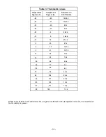
Page 53: ... k 20 4 48 4 k 15 5 36 4 k 10 14 27 6 k 5 23 21 k 0 32 16 3 k 5 41 12 7 k 10 50 10 k 15 59 7 8 k 20 68 6 2 k 25 77 5 k 30 86 4 k 35 95 3 2 k 40 104 2 6 k 45 113 2 2 k 50 122 1 8 k 55 131 1 5 k 60 140 1 2 k NOTE The resistance of the thermistors has a negative coefficient As the temperature increases the resistance of the thermistor decreases 51 ...

Page 54: ... 52 Component Location and Connector Views Switch freezer light Light Evaporator thermistor Evaporator Freezer thermistor Evaporator fan Defrost thermistor Heater defrost ...

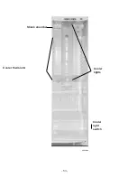
Page 55: ... 53 Shock absorber Cooler thermistor Cooler lights Cooler light switch GEA00980 ...

Page 56: ... 54 GEA00977 Condenser fan Jelly Roll ...

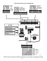
Page 57: ...ow Voltage Side 1 Black 2 Red 3 Blue 4 Purple 5 White 1 Blue Red 2 Yellow 3 Red White 4 Blue White 5 Blue J4 J3 J1 J2 8 Red 7 No es Usado 6 Black White 5 Yellow 4 Yellow Black 3 White 2 Blue White 1 Blue GEA00906 NOTE For more information see the Main Control Board Location Tables in the Diagnostics chapter 1 COMM 2 12V 3 COM 4 DI 5 DO 1 J4 5 1 J3 1 10 J2 1 8 J1 1 J5 9 6 ...

Page 58: ...LACK RED RED YELLOW RED BLUE WHITE PANEL SCREEN VER DIAGRAMA INDIVIDUAL BLACK RED YELLOW RED BLUE WHITE BLACK PRINCIPAL CONTROL PANEL VER DIAGRAMA INDIVIDUAL ORREJETA 4 OREJETA 2 OREJETA 1 CAFE ORANGE ORANGE ORANGE ORANGE ORANGE ...

Page 59: ...or more information see the Main Control Board Location Tables in the Diagnostics chapter PROCESSING UNIT SALIDAS COMPRESOR Y DESCONG ENTRADAS SWITCH PUERTA EXITS DEFROST PRE COOLING COOLING L1 COMP DEFR J8 J9 LINE J4 K4 COMP J12 PAILA_CLT N K3 DESCONG J6 DFZ DFF OCH COMUN AGUA TRITUR TALADRO 2 1 K5 QC J7 K7 PAILA CALT K1 TALADRO K2 C CR K6 AGUA ...

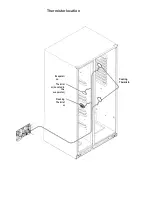
Page 60: ...Thermistor location Evaporati on Thermist or Located in the evaporator Freezing Thermist or Cooling Thermisto ...

Page 61: ......

Page 62: ...E PUERTA CONGELADOR CAFE RED WHITE LAMPARAS ENFRIADOR IMAN CALENTA DOREMP CAFE GRIS SWITCH CALENTADORES DESCONG ORANGE BLACK ORANGE PURPLE SWITCH LUZ ENFRIADOR CAFE PURPLE ORANGE CORDON ENERGIA AL ALAMBRADO MAQUINA CAFE YELLOW ORANGE AL ALAMBRADO DEL GABINETE WHITE VALVULA MA QUINA DE HIELO BLACK RED BLUE PURPLE WHITE BLACK WHITE NO SE USA YELLOW RED GRIS AL ALAMBRADO DEL GABINETE ORANGE VERDE YEL...

Page 63: ... 60 Illustrated Parts of the Catalog The scanned views of PSS25MGMABB are for general reference Always refer to the specific model for the latest piece information ...

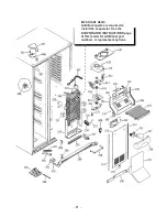
Page 64: ... 61 IMPORTANT NEWS Additional parts are required to install the evaporator See the EVAPORATOR INSTRUCTIONS page of this model for additional part numbers or replacement options ...

Page 65: ...red connection Apply a few drops of LokPrep a special cleaning solution and seal to the terminals of the pipe you wish to join The Lokring tool compresses the connector to ensure a tight mechanical connection The parts shown on the right are required to use the Lokring replacement method For additional information on how to use the Lokring call 1 800 848 7722 order publication 31 9067 Lokring Repa...

Reviews: