ELECTRIC SPECIFICATIONS
Temperature control………………………
Relay……………………………..…….....
Overload .................................................
Capacitor Func. (12 uF) .........................
Thermostat Overtemperature ................... Wiring
Wiring & Thermostat heat defrost .....
Heater Discong. & Clamp ..........
Fan Motor Condenser .....................
Fan Evaporator Engine ........................
Main Board ..................... ...................
Dispenser Board ..................................
Thermistor (EV) ............................................
Thermistor (FZ) ............................................
Thermistor (FF) ............................................
Thermistor (FF) ............................................
Fans Fan Motor ........................................
Shock absorber……………………………
wr55x10023
wr07x10031
wr08x10025
wr62x10079
wr50x10015
wr23x10142
wr51x10030
wr60x10042
wr60x10043
wr55x10024
wr55x10029
wr55x10025
wr55x10026
wr55x10027
wr55x10028
wr60x10051
Specifications
R
e
l
é
.
.
.
.
.
.
.
.
.
.
DISCONNECT THE POWER CORD BEFORE
SERVICING.
-IMPORTANT-
CONNECT
ALL
EARTHED APPLIANCES AGAIN
All parts of this device capable of conducting electrical
current are grounded. If the wires, bolts, fasteners,
fasteners, nuts and ground washers used to complete a
grounding are removed for service, they must be returned
to their original position and be properly tightened.
IMPORTANT SAFETY NOTICE
This information is intended to be used by people
who have an adequate background in electrical,
electronic and mechanical experience. Any
attempt to repair an appliance can result in
personal injury or property damage. The
manufacturer or seller cannot be responsible for
the interpretation of this information, nor can it
assume any responsibility in relation to its use.
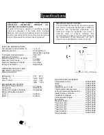
ELECTRIC SPECIFICATIONS
Temperature Control (Position 5) ................
Defrosting Control ...........................
…….
Thermostat Overtemperature ...................
Defrosting
Thermistor………....................
Electric Capacity: 115V, AC 60 Hz .........
Maximum Current Leak ..................
……
Maximum Resistance to Earth ................
Energy consumption……………………..
OPERATION WITHOUT LOAD
MID / MID Control Position
and Environment of:
Refrigerator, ° F .................................
Freezer, ° F .................................
….
Func. Time,% ....................................
REFRIGERATION SYSTEM
Refrigerant charge (R134a) ..................
Compressor……………………………...
Minimum Compressor Capacity ............
Minimum Equalized Pressure
@ 70 ° F ....................................
………
@ 90 ° F .................................................
Abrir en Google Traductor
7-(-11)°F
60 hrs @ 35 min
without door openings
140-110°F
65°F
11.6 Amp
0.50 mA.
0.14 Ohms
KWH/month
70°F 90°F
34-40 34-40
(-3) 3 (-3) 3
<45% <70%
4.75 onzas
690 BTU/hr
22 pulgadas
48 PSIG
60 PSIG
Summary of Contents for GSS21 Series
Page 41: ......
Page 42: ......
Page 43: ......
Page 44: ......
Page 45: ......
Page 46: ......
Page 47: ......
Page 48: ...The Condenser Fan Does Not Work ...
Page 49: ......
Page 50: ......
Page 51: ......
Page 52: ......
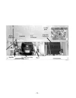
Page 55: ... 53 Shock absorber Cooler thermistor Cooler lights Cooler light switch GEA00980 ...
Page 56: ... 54 GEA00977 Condenser fan Jelly Roll ...
Page 61: ......


