11
www.massportal.com
3.4.
Calibration
1)
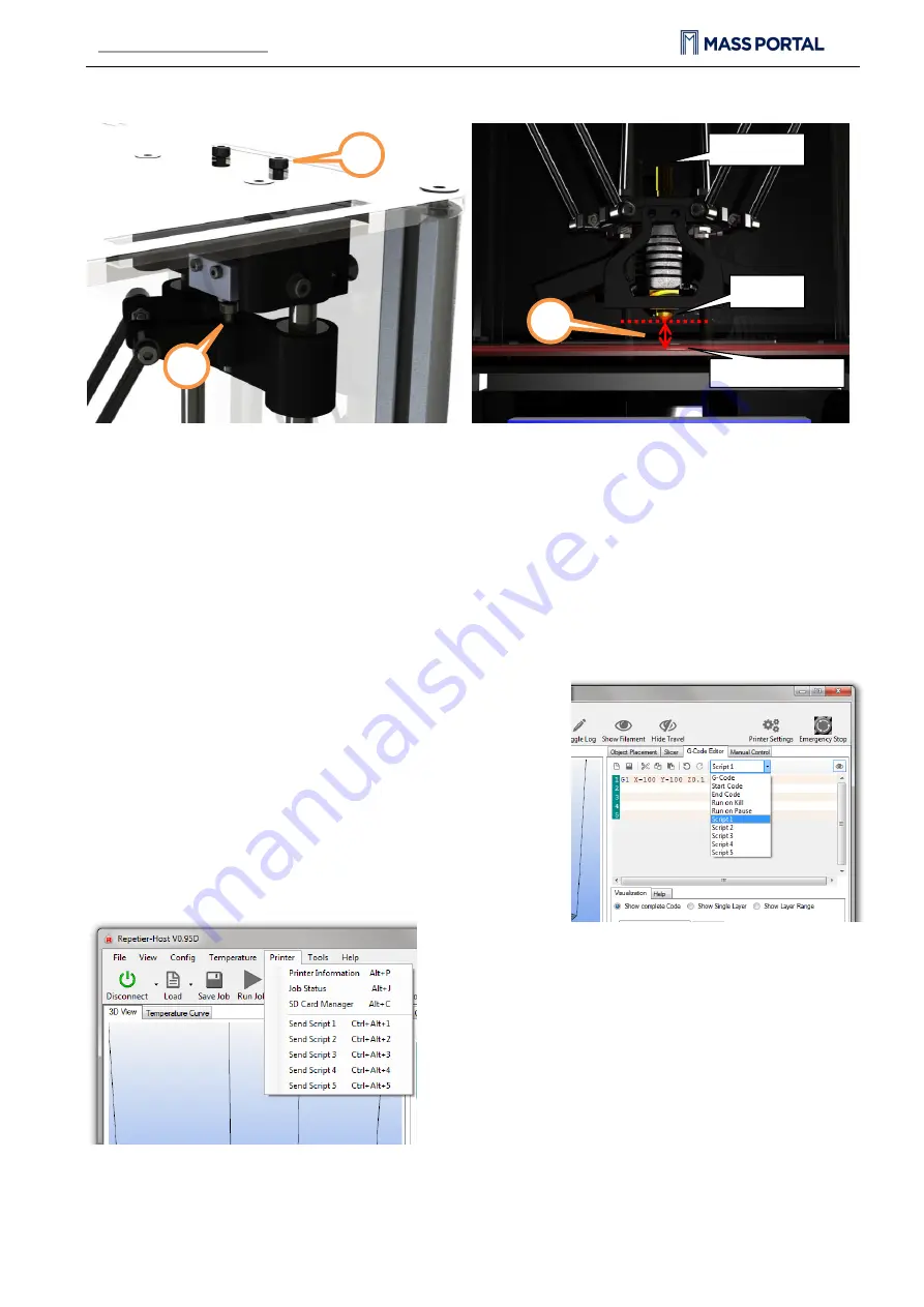
Timing belt adjustment
. Use the two screws at the top to adjust the timing belt. By turning the screws
clockwise the timing belt is tightened, but by turning them counter-clockwise the timing belt is released. The
screws must both be turned equal amount of turns. You can use a marker to mark the position of screws. The
timing belts on each axis must be checked by hand – it must be able to push them lightly together, but they must
not be too tight or too loose.
2)
Extruder gap height in relation to printing surface
. In case the printing head’s extruder is not at equal
height from every position against the printing surface, it must be calibrated. One of the symptoms is uneven
adhesion of the first extruded layers when printing a 3D object. Use the screws on top of each axis sliders (refer
to illustration in chapter 2.1 for axis labels). By turning the screw
clockwise
the gap between extruder and
printing surface is
extended
, by turning it counter-clockwise the gap is reduced. It is rather likely that the
calibration must be made after changing the extruder or after
transportation.
To ease the calibration use
Scripts
from
G-Code Editor
in the
Repetier-Host software:
Script 1
G1 X-100 Y-100 Z0.1 F4000
; place near the X axis column
Script 2
G1 X100 Y-100 Z0.1 F4000
; place near the Y axis column
Script 3
G1 X0 Y100 Z0.1 F4000
; place near the Z axis column
Script 4
G1 X0 Y0 Z0.1 F4000;
the center of the printing surface
You can run these scripts by pressing
Ctrl
+
Alt
+[Num] where [Num]
is the script number.
By sending each script command you can check the gap at the
corresponding head placement. It must be 0.1 mm. You can
check the height by placing a piece of common plain paper
between the extruder and a printing surface (before sending
the command). Move the paper around and notice the
resistance – if it is unable to move it means that the gap is too
tight, if it is too easy to move the paper under the extruder then
the gap is too big. Adjust the screws accordingly. Note that one
full turn of a screw moves the slider by 0.5 mm, but the ratio
between the turns of a screw and the extruder’s gap is not
exactly 1:1.
1
1
1
1
2
1
2
1
Extruder
Printing surface
Pipe binding
2
1


