background image

P. 36 / 68

920MHz Band Wireless Device (Korea)  USERS MANUAL  EM-9121 Rev. 1

6.1.2  EXECUTING CHANNEL NOISE SCAN

Perform the channel noise scan according to the following procedure.
Do not turn off the power of the wireless device or remove the mini USB cable during the measurement, or an error message will 
appear and the channel noise scan tool will be forcibly terminated.

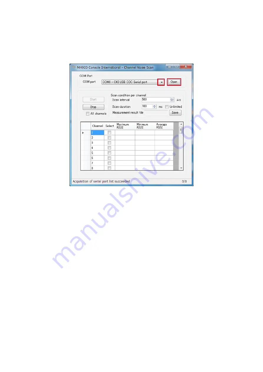
1)  Click the pull-down button in the “COM port” column, select the COM port to which the wireless device is connected, and click 

[Open].

Figure 6.9 Selecting COM port

Summary of Contents for WL40EW2KR

Page 1: ...s Transparent 920MHz Band Wireless Device Korea USERS MANUAL http www m system co jp 5 2 55 Minamitsumori Nishinari ku Osaka 557 0063 JAPAN Tel 81 6 6659 8201 Fax 81 6 6659 8510 E mail info m system c...

Page 2: ...AINTENANCE CONSOLE 12 5 1 1 APPLICABLE VERSION 12 5 2 INSTALLING UNINSTALLING MAINTENANCE CONSOLE AND USB DRIVER 12 5 2 1 INSTALLING MAINTENANCE CONSOLE 13 5 2 2 INSTALLING USB DRIVER 17 5 2 3 UNINSTA...

Page 3: ...57 7 1 10 STATION NUMBER AND SHORT ADDRESS 58 7 1 11 EXAMINING PACKET FILTERING SETTINGS 59 7 1 12 EXAMINING FIXED ROUTE SETTINGS 59 7 1 13 NETWORK SCALE AND QUALITY SETTINGS 60 7 1 14 PASSWORD TO CO...

Page 4: ...mpany The symbols such like and are not described in this manual Notes M System is not responsible for any effect caused by the results of using the products and this manual M System is not responsibl...

Page 5: ...es with a child device via a 920 MHz band wireless device using Modbus TCP and RTU protocol and also communicates with slave devices in multi drop connection RS 485 LAN cable STP cable PC Modbus Maste...

Page 6: ...interface Agency certification KCC Frequency 920 MHz band 920 5 923 5 MHz Bandwidth 400 kHz Max transmission power 12 5 mW Baud rate Max 100 kbps Max packet size 2048 bytes Max transmission distance...

Page 7: ...w and take necessary actions such as designing the network configuration setting wireless devices etc 1 EXAMINING WIRELESS NETWORK CONFIGURATION 2 SELECTING DEVICES 3 PREPARING MAINTENANCE CONSOLE 4 P...

Page 8: ...nsmitted from the child device in its route information table 2 With this table the parent device automatically generates the downstream network route source routing to the child device a a Generating...

Page 9: ...series WL40EW2KR connects with an upper device e g data acquisition device via TCP IP to collect data from remote I Os connected to wireless child devices Figure 4 1 Parent device Table 4 1 Specificat...

Page 10: ...data received wirelessly to devices connected by wire Figure 4 2 Child device Table 4 2 Specifications of child device ITEM SPECIFICATIONS Power input 24V DC or 12V DC Current consumption 24V DC 70mA...

Page 11: ...in a high location which is effective for the reachability of radio wave The specifications of the antennas are as shown in the table below Table 4 3 Specifications of antennas for wireless devices I...

Page 12: ...of the maintenance console applicable to the wireless communication modules Table 5 1 Maintenance console version Communication module version Maintenance console version Ver f4 3 0 Ver 4 32 or later...

Page 13: ...in the extracted files and start the setup wizard When the Setup Wizard screen appears click Next Figure 5 1 Setup wizard Note When Microsoft NET Framework 4 is not installed a message box that requir...

Page 14: ...nd click Next The default location of the installation folder is as follows depending on the operating systems of the PC For 32 bit OS C Program Files OKI MH920 Console International For 64 bit OS C P...

Page 15: ...t Korea KR and click Next Figure 5 5 Set Country dialog box 6 When the Ready to Install the Program dialog box appears select Everyone and click Install Figure 5 6 Ready to Install the Program dialog...

Page 16: ...920MHz Band Wireless Device Korea USERS MANUAL EM 9121 Rev 1 7 After the InstallShield Wizard Completed message box appears click Finish to finish the installation Figure 5 7 Installation Complete mes...

Page 17: ...PC stating that the driver of the wireless device cannot be found If the driver installation dialog box appears cancel without installing at this time After steps 1 to 3 take steps 4 5 and 6 if the o...

Page 18: ...s 10 7 Right click the start button and select Control Panel 8 Select Device Manager from the list and expand Ports COM LPT 9 Right click USB Serial Device COM x to display a menu and select Update Dr...

Page 19: ...Serial port Properties dialog box appears click Update Driver to activate the Update Driver Software wizard Figure 5 10 USB CDC serial port properties 11 When the Update Driver Software dialog box app...

Page 20: ...le and click Next The default location of the installation folder depends on the operating systems of the destination PC For 32 bit OS C Program Files OKI MH920 Console International USB_Driver For 64...

Page 21: ...his driver software anyway to continue the installation Figure 5 14 Windows Security 14 Installing driver then Installation completed messages appear in order 15 Confirm that the driver has been succe...

Page 22: ...Manager Note Remember this COM port number to be used in COM port setting on the maintenance console Figure 5 16 shows an example where the port of OKI USB CDC Serial port is COM5 The USB driver insta...

Page 23: ...Start the maintenance console according to the following procedure 1 Double click the shortcut MH920 Console International on the desktop to start the maintenance console Figure 5 17 Shortcut of MH920...

Page 24: ...is correctly connected to the PC with the maintenance console via a mini USB cable 5 3 1 1 COM PORT Set a COM port through which the maintenance console communicates with the wireless device 1 Click t...

Page 25: ...quired for connecting to the wireless device 1 Enter a password in the New password field and enter the same in the New password confirmation field Refer to 7 EXAMINING PARAMETERS OF WIRELESS DEVICES...

Page 26: ...d entry when connecting to a wireless device from the maintenance console can be set 1 Set a password and Omit password Figure 5 24 Omit password setting Table 5 4 Omit password setting items ITEM SET...

Page 27: ...27 68 920MHz Band Wireless Device Korea USERS MANUAL EM 9121 Rev 1 2 Click Set Figure 5 25 Omit password setting 3 A message box appears if the Omit password setting has been changed correctly Click O...

Page 28: ...3 1 4 COUNTRY SETTING The country where the Maintenance Console is started and used is set 1 Click the pull down button in the Country column to show the country list Figure 5 26 Country setting 2 Se...

Page 29: ...M 9121 Rev 1 2 The country setting has been applied and setting completion messages appear Click OK on each message Figure 5 28 Country setting completion message Figure 5 29 Country setting completio...

Page 30: ...used Figure 5 31 Maintenance Console Main screen 5 4 2 ROUTER CONFIGURATION Not used Figure 5 32 Maintenance Console Main screen 5 4 3 UPDATING FIRMWARE OF WIRELESS COMMUNICATION MODULE Do not update...

Page 31: ...each wireless device from the normal mode to the measurement mode To switch the mode refer to 6 3 TERMINATING MEASUREMENT TOOL on page 51 Note 2 The wireless connection is disconnected when the PAN ID...

Page 32: ...RTING CHANNEL NOISE SCAN 1 Connect a wireless device to the PC with the maintenance console via a mini USB cable and turn on the power of the device 2 Start the maintenance console and click Environme...

Page 33: ...1 Rev 1 4 Close the Environment setup screen and click Measurement tool on the main screen Figure 6 3 Maintenance console main screen 5 When the following screen appears check Channel noise scan mode...

Page 34: ...required to connect with the wireless device Enter the password and click Connect Figure 6 5 Password entry 7 When the following message appears click OK Figure 6 6 Confirming channel noise scan star...

Page 35: ...P 35 68 920MHz Band Wireless Device Korea USERS MANUAL EM 9121 Rev 1 10 Channel Noise Scan screen appears Figure 6 8 Channel noise scan...

Page 36: ...procedure Do not turn off the power of the wireless device or remove the mini USB cable during the measurement or an error message will appear and the channel noise scan tool will be forcibly terminat...

Page 37: ...ut for 100 msec at 500 s interval per channel Number of times of channel noise scan per channel scan duration msec 1000 scan interval s Figure 6 10 Specifying scan interval and duration When Unlimited...

Page 38: ...e are as follows unless they are specified Folder chnscan CH Noise_Log File name CHN_yymmdd HHMMSS csv yy year mm month dd date HH hour MM minute SS second Table 6 1 Measurement result file contents I...

Page 39: ...channels have low RSSI values Refer to 7 1 3 RADIO CHANNEL NUMBER on page 54 for details Figure 6 14 Measurement result Table 6 2 Measurement result contents ITEM EXPLANATIONS Maximum RSSI Max RSSI v...

Page 40: ...sured 1 Setting sender Set a channel to measure 2 Setting receiver Set the same channel as the sender Figure 6 15 Configuration of communication test 6 2 1 SETTING SENDER Set the first wireless device...

Page 41: ...ck the pull down button in the COM port column select the COM port to which the device is connected and click Set Figure 6 17 Environment setup 6 Close Environment setup screen and click Measurement t...

Page 42: ...k Change mode Figure 6 19 Selecting communication test Sender 8 When Omit password is set to No on Environment setup screen the password is required to connect to the wireless device Enter the passwor...

Page 43: ...heck Communication test mode Sender and click Launch tool Figure 6 22 Starting communication test Sender 12 When the following screen appears click the pull down button in the COM port column select t...

Page 44: ...Load from module To specify a new channel number click the pull down button in the Radio channel number column select a channel and click Save to module Figure 6 24 Setting sender channel number 14 A...

Page 45: ...6 3 TERMINATING MEASUREMENT TOOL on page 51 and return to the normal mode 1 Both sleeve and rooftop antennas can be used 2 Connect the device to the PC with the maintenance console using a mini USB ca...

Page 46: ...onnect to the wireless device Enter the password and click Connect Figure 6 28 Password entry 6 When the following message appears click OK Figure 6 29 Confirming communication test receiver startup 7...

Page 47: ...to be set as a receiver is connected and click Open Figure 6 31 Selecting COM port 10 Specify a radio channel number To use the channel already set in the device click Load from module 11 To specify a...

Page 48: ...121 Rev 1 6 2 3 MEASURING RSSI AND PER Execute the measurement with the wireless device set as a receiver 1 Specify Measurement duration within the range of 1 to 600000 seconds on Communication test R...

Page 49: ...MM minute SS second Table 6 3 Measurement result file contents ITEM EXPLANATIONS Maximum RSSI dBm Max RSSI value in the measurement result Minimum RSSI dBm Min RSSI value in the measurement result Ave...

Page 50: ...ate in the measurement duration Receive count Number of packets received in the measurement duration Packet Number Latest received packet number number of the packet the sender transmitted RSSI RSSI v...

Page 51: ...ck Close button in the COM port column on the channel noise scan or communication test Sender or Receiver screen and confirm that x button in the upper right corner is activated Click x then click OK...

Page 52: ...ick Change mode Figure 6 38 Normal mode selected 4 When the following message appears click Yes Figure 6 39 Switching measurement mode 5 The wireless device reboots in the normal mode and the followin...

Page 53: ...Set in a parent device MAC address list Set in a parent device Connection refusal list Set in a parent device Low speed moving mode Set in child devices Prefix Set in a parent device Short address Fi...

Page 54: ...range as shown in Table 7 3 PAN ID Table 7 3 PAN ID DEVICE SETTING SPECIFICATIONS RANGE REMARKS Parent Required Hexadecimal 4 digits 0x0001 0xFFFE Set to a value that does not overlap with that of ot...

Page 55: ...and are usable 7 1 5 TRANSMITTER POWER OUTPUT The radio wave reachable distance changes depending on the transmitter power output The transmitter power output is selected from 12 5 mW 5 mW 1 mW and 0...

Page 56: ...ccordance with the table below Table 7 8 Encryption key DEVICE SETTING SPECIFICATIONS RANGE REMARKS Parent Required Hexadecimal 32 digits Child Required Hexadecimal 32 digits Set the same key as that...

Page 57: ...es 6 Each child device notifies the parent device of its own IPv6 address 7 The parent device notifies the child device of the availability of the IPv6 address Hereafter the parent device manages the...

Page 58: ...ode is a method to assign the station numbers of the Modbus devices to the short addresses of the child devices within the specified range 1 Max No of multi drops Set to the child devices capable of m...

Page 59: ...ng the devices with the same PAN ID as explained in 7 1 2 PAN ID GROUP NUMBER on page 54 However the fixed route function enables a device to connect with a specified destination regardless of momenta...

Page 60: ...uired Not required Fast join mode child devices only 25 child devices 0 sensor V3 compatible mode standard 15 child devices 10 sensors Fixed value Note Standard 15 child devices 10 sensors in connecti...

Page 61: ...ces to pass through Parent Device No of times of access 1 No of times of access 2 No of times of access 5 Number of hops 1 Number of hops 2 Number of hops 3 Child Device 1 Child Device 5 Child Device...

Page 62: ...le below for the configuration of the parent device Table 8 1 Configuration of parent device MODEL MANUAL WL40EW2KR WL40EW2x Operating Manual EM 9115 B 8 2 CHILD DEVICE Refer to the manual as shown in...

Page 63: ...h the polarization planes of a parent and child devices Install an antenna with its direction perpendicular to the ground because its directionality is omnidirectional to the horizontal plane Differen...

Page 64: ...EEVE ANTENNA FOR WIRELESS I O WL40KR SERIES The following figures show the directionality of the sleeve antenna The sleeve antenna is omnidirectional in a horizontal plane E_PLANE 915MHz 0 30 60 90 12...

Page 65: ...tenna is omnidirectional in a horizontal plane X axis Y axis Z axis XY plane XZ plane 10 10 20 30 40 20 30 10 10 0 0 0 30 60 90 120 150 180 210 240 270 300 330 E Plane H Plane 10 10 20 30 40 20 30 10...

Page 66: ...nel radius is obtained by Equation 9 1 as shown in Table 9 1 when the antenna distance is 100 m 200 m 300 m 500 m and 1000 m Table 9 1 Fresnel radius Distance between antennas 100 m 200 m 300 m 500 m...

Page 67: ...ion path diffracted wave reflected wave transparent wave can affect radio communication Radio wave can travel directly to a receiver but often reaches the receiver after being reflected by surrounding...

Page 68: ...ireless Device Korea USERS MANUAL EM 9121 Rev 1 10 MEASUREMENT OF RADIO WAVE ENVIRONMENT Perform the measurements described in 6 PRELIMINARY MEASUREMENT OF RADIO WAVE ENVIRONMENT again with the instal...

Reviews: