


R7M-RS4
P. 2 / 7
EM-7803-C Rev.5
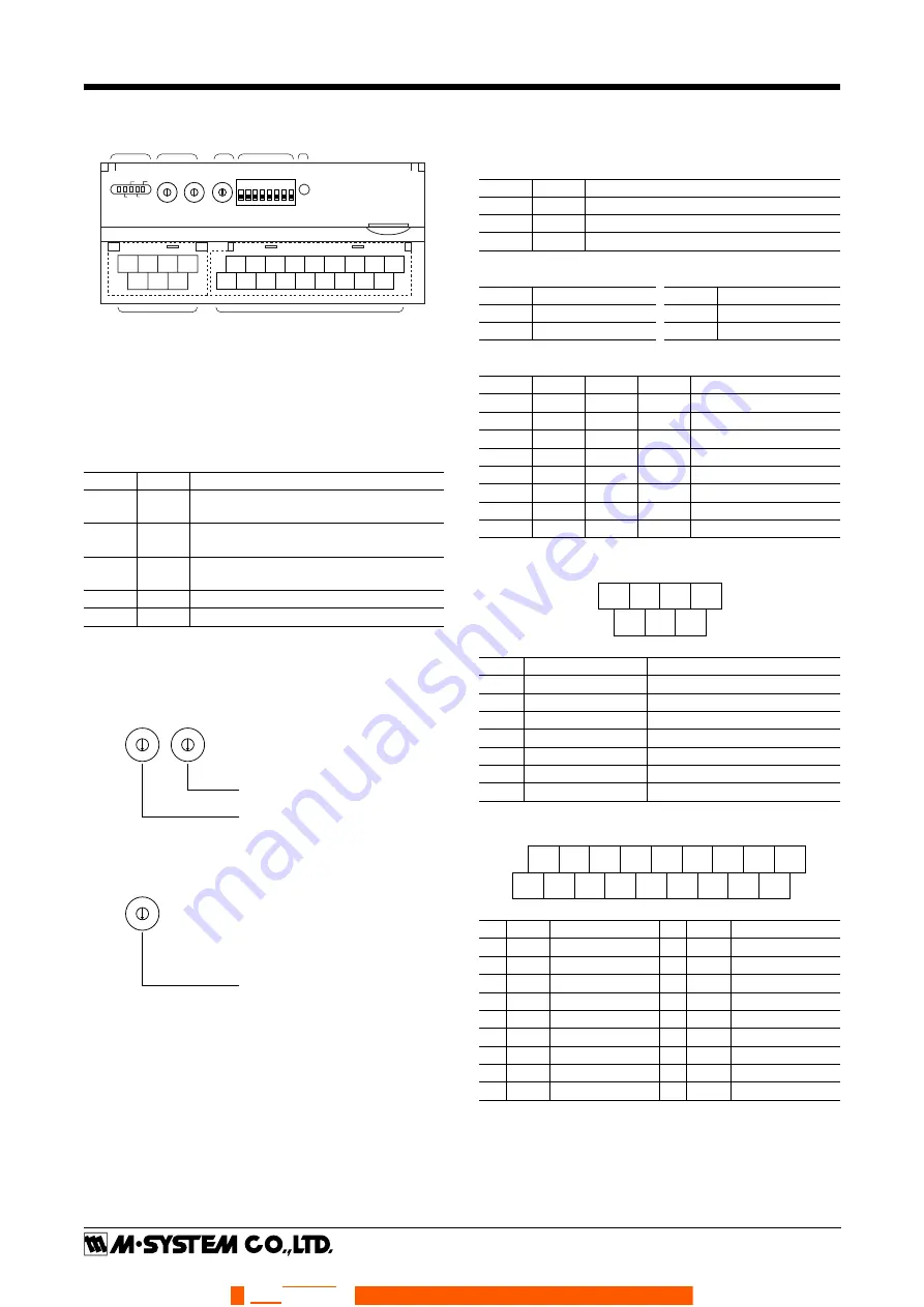
COMPONENT IDENTIFICATION
5
4
3
2 1 0 9
8
7
6
5
4
3
2 1 0 9
8
7
6
5
4
3
2 1 0 9
8
7
6
ERR
RD
RUN
SD
PWR
X10
X1
NODE ADD.
B.RATE
CNFG.
1
2
3
4
5
6
7
8
4
5
6
7
1
2
3
10 11 12 13
2
3
4
1
15 16 17 18
7
8
9
6
14
5
(A) Status Indicator LED
(B) Node Address Setting Rotary SW
(C) Baud Rate Setting Rotary SW
(D) Operating Mode Setting DIP SW (SW1)
(E) PC Configurator Jack
(F) Modbus, Power Supply Terminals
(G) Input Terminals
(A)
(F)
(G)
(B)
(C)
(D)
(E)
■
STATUS INDICATOR LED
ID
COLOR FUNCTION
PWR
Red
Turns on when the internal 5V is supplied
normally.
RUN
Red
Turns on when the data is received nor-
mally.
ERR
Red
Turns on when the received data is abnor-
mal. Blinks when setting is abnormal.
SD
Red
Turns on when the module is transmitting.
RD
Red
Turns on when the module is receiving.
■
NODE ADDRESS
Node Address is selected between 1 and 99 in decimal. The
left switch determines the tenth place digit, while the right
switch does the ones place digit of the address.
5
4
3
2
1
0
9
8
7
6
5
4
3
2
1
0
9
8
7
6
Node Address Setting (x1)
Factory setting : 00
Node Address Setting (x10)
■
BAUD RATE
Baud Rate is selected with the rotary switch.
5
4
3
2
1
0
9
8
7
6
Baud Rate Setting
0 : 38.4 kbps (factory setting)
1 : 19.2 kbps
2 : 9600 bps
3 : 4800 bps
■
EXTENSION MODULE
Combinations with all extension modules are selectable.
■
OPERATING MODE
(*) Factory setting
•
Extension (SW1-1, 1-2)
SW1-1
SW1-2 EXTENSION
OFF
OFF
No extension (*)
ON
OFF
Discrete input, 8 or 16 points
OFF
ON
Discrete output, 8 or 16 points
• Conversion Rate (SW1-3) • Burnout (SW1-4)
SW1-3 Conversion rate
SW1-4 Burnout
OFF
250 msec. (*)
OFF
Upscale (*)
ON
500 msec.
ON
Downscale
•
RTD Type (SW1-5, 1-6, 1-7, 1-8)
SW1-5
SW1-6
SW1-7
SW1-8 RTD TYPE
OFF
OFF
OFF
OFF
Pt 100 (JIS ’97/IEC) (*)
ON
OFF
OFF
OFF
Pt 100 (JIS ’89)
OFF
ON
OFF
OFF
JPt 100 (JIS ’89)
ON
ON
OFF
OFF
Pt 50 (JIS ’81)
OFF
OFF
ON
OFF
Ni 100
ON
OFF
ON
OFF
Cu 10 (25°C)
OFF
OFF
OFF
ON
Cu 50
ON
ON
ON
ON
PC Configurator setting
■
POWER SUPPLY, MODBUS TERMINAL ASSIGNMENT
4
DA
5
DG
6
+24V
1
DB
2
SLD
3
FG
7
0V
NO.
ID
FUNCTION, NOTES
1
DB
----
2
SLD
Shield
3
FG
FG
4
DA
----
5
DG
----
6
+24V
Power input (24V DC)
7
0V
Power input (0V)
■
INPUT TERMINAL ASSIGNMENT
10
INA0
11
INb0
12
INA1
1
NC
2
INB0
3
NC
13
INb1
4
INB1
14
NC
5
NC
15
INA2
6
NC
16
INb2
7
INB2
17
INA3
8
NC
9
INB3
18
INb3
NO.
ID
FUNCTION
NO.
ID
FUNCTION
1
NC
No connection
10 INA0 RTD 0-A
2
INB0 RTD 0-B
11 INb0 RTD 0-b
3
NC
No connection
12 INA1 RTD 1-A
4
INB1 RTD 1-B
13 INb1 RTD 1-b
5
NC
No connection
14
NC
No connection
6
NC
No connection
15 INA2 RTD 2-A
7
INB2 RTD 2-B
16 INb2 RTD 2-b
8
NC
No connection
17 INA3 RTD 3-A
9
INB3 RTD 3-B
18 INb3 RTD 3-b
056 222 38 18
www.sentronic.com
SENTRONIC
AG


