M6NPS2
5-2-55, Minamitsumori, Nishinari-ku, Osaka 557-0063 JAPAN
Phone: +81(6)6659-8201 Fax: +81(6)6659-8510 E-mail: [email protected]
EM-7914 Rev.5 P. 2 / 3
TERMINAL CONNECTIONS
Connect the unit as in the diagram below or refer to the connection diagram on the side of the unit.
■
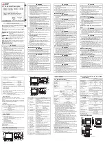
EXTERNAL DIMENSIONS unit: mm (inch)
102 (4.02)
7.5 (.30)
DIN RAIL HOOK
102 (4.02)
[1 (.04)]
8–M3
SCREW TERMINAL
WIRE INSERTION ANGLE
: approx. 35°
SCREWDRIVER
*
INSERTION ANGLE
: approx. 55°
SCREWDRIVER
INSERTION ANGLE
: approx. 40°
DIN RAIL
35mm wide
5
6
7
8
1
2
3
4
• When mounting, no extra space is needed between units.
*
Screwdriver stem diameter: 6 mm (.24”) or less
■
CONNECTION DIAGRAM
CONNECTOR
+
–
+
+
–
–
–
1
3
2
4
+
POWER SOURCE 2
5
7
8
6
POWER SOURCE 1
24V DC POWER