M-system M2EXS Operating Manual Download Page 4

M2EXS

5-2-55, Minamitsumori, Nishinari-ku, Osaka 557-0063 JAPAN
Phone: +81(6)6659-8201 Fax: 

+81(6)6659-8510  E-mail: [email protected]

EM-5137-B Rev.1  P. 4 / 18
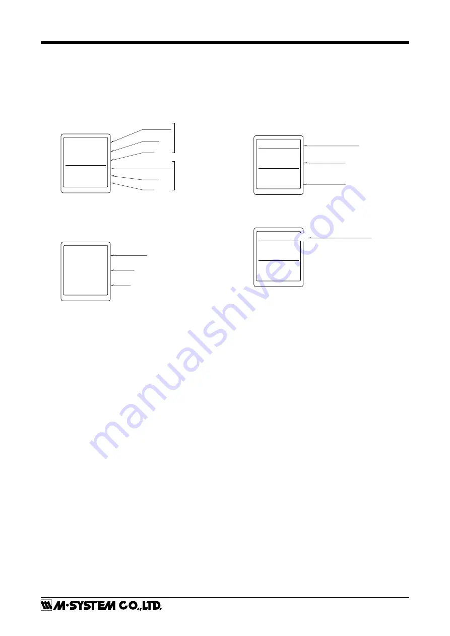
SCREEN DISPLAY


DISPLAY IN MEASURING MODE

• 

Double tiered display

The unit can select and display any two items out of input 
engineering value, input scaling value, % value*, output en-
gineering value, and output scaling value.

* Percent value for input.

INP


(Scaling)

L / min

12.34

50.00

PERCENT

%

Item name

Value

Unit

Item name

Value
Unit

Upper

Lower

• 

Single tiered display

When displayed item is one, it is available to show big char-
acters in single tiered display.

INPUT

mA

20.00

Value

Unit

Item name

Refer to the Display setting of the Advanced mode for 
settings.


DISPLAY IN EACH SETTING MODE

For each setting, current values of setting parameter, ITEM 
number and setting value are indicated. During setting, 
‘(Setting)’ is indicated at the side of data display.
If the power is mistakenly shut down during setting, set-
ting values are discarded. (Return to the value before set-
ting change.)  Setting display previously displayed before 
power shutdown is indicated at next power up.

Brightness
ITEM

91

DATA (Setting)

3

Setting parameter

Item number

Setting Value

The long setting parameter is indicated by scrolling.

ITEM

14

DATA 

0.00

Indicated by scrolling


0%


input  scaling


DISPLAY TIMEOUT

When there is no operation within the setting time of dis-
play timeout, display is turned off. Pressing Mode, Set, Up 
or Down button or occurring error enables to return from 
display off.  Set ‘0’ to display ‘always on’.

Summary of Contents for M2EXS

Page 1: ...f this unit when it is integrated in a panel system The user may have to review the CE requirements in regard to the whole system and employ additional protective measures to ensure the CE conform ity...

Page 2: ...ving the socket push down the DIN rail adaptor utilizing a minus screwdriver and pull WALL MOUNTING Refer to the drawings in the shown below TERMINAL CONNECTIONS Connect the unit as in the diagram bel...

Page 3: ...ing changeable state used to enter save the setting value Used to move on through digits of setting value for input output scaling at setting changeable state Up Button Used to shift through setting p...

Page 4: ...tting of the Advanced mode for settings DISPLAY IN EACH SETTING MODE For each setting current values of setting parameter ITEM number and setting value are indicated During setting Setting is indicate...

Page 5: ...RT POWER ON Measuring Mode Hold down Mode Button for 2 seconds Hold down Mode Button for 2 seconds Basic Setting Mode Option Mode Advanced Mode Hold down Mode Button for 2 seconds Hold down Mode Butto...

Page 6: ...ing value to set value Keeping pressing Down button enables to decrease the value continuously Operation of input setting parameter 06 Angle offset is set by teach The present input value is displayed...

Page 7: ...ds Set Set Set Set Set Set Set Set Set Set Set Set Set Set Set Set Set Set Set Set Set Set Up Down Up Down Up Down Up Down Up Down Up Down Up Down Up Down Up Down Up Down Up Down Up Down Up Down Up Do...

Page 8: ...input scaling 99999 999999 100 00 16 Input decimal point No decimal point The number of decimal places 1 5 2 places of decimals 17 Output range 0 20mA 5 5V 10 10V 0 20mA 18 0 output setting 0 000 19 0...

Page 9: ...the unit SETTING VALUE DESCRIPTION INITIAL VALUE 0 20 mA Output 0 20 mA DC 0 20 mA 5 5 V Output 5 5 V DC 10 10 V Output 10 10 V DC When output range is changed turn the power off and then set the outp...

Page 10: ...ase it by pressing Up and Down button Press and hold them enables to change value continuously 1 Pressing and holding Mode button more than 2 seconds or turning off the power enable to exit loop test...

Page 11: ...ble unit Set Set Hold down Mode button for 4 seconds Hold down Mode button for 2 seconds Set Set Set Set Set Set Set Set Set Set Set Up Down Up Down Up Down Up Down Up Down Up Down 1 1 0 30 5 000 5 00...

Page 12: ...to user s unit setting display A unit can be created by using any characters Up to 13 characters available 1 Up and Down button enables to move on selected characters Set button enables to select a ch...

Page 13: ...wn Mode button for 6 seconds Hold down Mode button for 2 seconds Set Set Set Set Set Set Set Set Up Down Up Down Up Down Up Down Up Down Up Down 1 1 4 0 1 60 OFF RESET Lock Unlock Advanced Mode Parame...

Page 14: ...Adjust brightness of display It is available to set the range between 1 darkest 4 brightest Initial value 4 92 Display timeout Set the time to off the display when there is no operation within a certa...

Page 15: ...de button for 8 seconds Hold down Mode button for 2 seconds Set Set Set Set Set Set Set Set Set Set Set Set Set Up Down Up Down Up Down Up Down Up Down Up Down Up Down Up Down Disable Enable 2 32 5 00...

Page 16: ...een 5 to 105 for both X and Y For X it is required to set in ascending order from X001 Be sure that if it is set with other than ascending order cor rect conversion is not carried out Initial value X0...

Page 17: ...rror occurs only high priority error is displayed Order of priority is EEPROM ERROR OVER RANGE SCALING ERROR in descending order ERROR MESSAGES DISPLAY SETTING INPUT ENGINEERING UNIT VALUE INPUT SCALI...

Page 18: ...ed in the users manual of the M2ECFG configurator software Or follow the procedure shown below INPUT FINE ADJUSTMENT Set the input signal to 0 and adjust the input to 0 by 06 Angle offset OUTPUT FINE...

Reviews: