

48NAT
5-2-55, Minamitsumori, Nishinari-ku, Osaka 557-0063 JAPAN
Phone: +81(6)6659-8201 Fax: +81(6)6659-8510 E-mail: [email protected]
EM-9433 Rev.8 P. 5 / 8
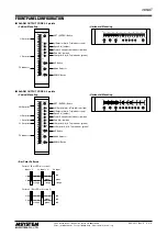
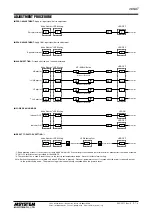
■
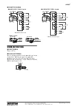
CONNECTION DIAGRAM
+
–
T/C
comp. leadwire
+
–
T/C
comp. leadwire
12
13
14
15
16
12
13
14
15
16
LLa
11
La
LLb
Lc, LLc
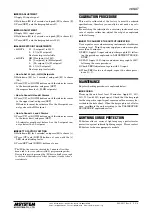
LOAD
Inductive
Load (Coil)
Varistor or
CR Circuit
•
DC Powered
LOAD
Inductive
Load (Coil)
Diode, Varistor or
CR Circuit
■
Relay Protection
• AC Powered
7
8
9
8
9
10
HHa
7
Hc, HHc
HHb
Ha
HH OUTPUT
H OUTPUT
LL OUTPUT
L OUTPUT
■
ALARM OUTPUT CODE 2: 2 points
U
■
ALARM OUTPUT CODE 4: 4 points
+
–
CJC
SENSOR
metal leg
model: CJM
*
*
Deleted with B thermocouple
+
–
CJC
SENSOR
metal leg
model: CJM
*
*
Deleted with B thermocouple
U(+)
V(–)
POWER
U(+)
V(–)
La
Lb
Lc
Hc
Ha
Hb
H OUTPUT
L OUTPUT
POWER
3
2
4
3
2
4
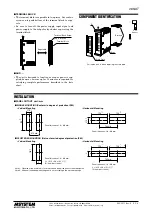
WIRING INSTRUCTIONS
■
SCREW TERMINAL
Torque: 0.6 N·m
■
SOLDERLESS TERMINAL
Refer to the drawing below for recommended ring tongue
terminal size. Spade tongue type is also applicable.
Applicable wire size: 0.25 to 1.65 mm
2
(AWG 22 to 16)
Recommended manufacturer: Japan Solderless Terminal
MFG.Co.Ltd, Nichifu Co.,ltd
6 (.24) max
3.3 (.13) max
mm (inch)


