

48NAT
5-2-55, Minamitsumori, Nishinari-ku, Osaka 557-0063 JAPAN
Phone: +81(6)6659-8201 Fax: +81(6)6659-8510 E-mail: [email protected]
EM-9433 Rev.8 P. 6 / 8
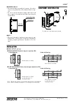
FRONT PANEL CONFIGURATION
■
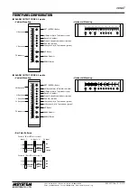
ALARM OUTPUT CODE 2: 2 points
■
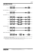
ALARM OUTPUT CODE 4: 4 points
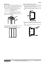
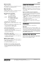
• Bar Color Patterns
Pattern 1 (Bar LED color code 1)
orange
orange
green
orange
Input < L
L < Input < H
H < Input
green
red
H
L
Pattern 2 (Bar LED color code 2)
orange
green
green
red
red
red
H
L
50
40
30
20
10
0
-10
-20
-30
-40
-50
°C
%
100 SET
H
S
•
Z
L
90
80
70
60
50
40
30
20
10
0
SET (ENTER) Button
H Setpoint Adj. & Trip Indicator (red)
Span Adj. (amber)
Power Saving Mode Indicator (amber)
Zero Adj. (amber)
L Setpoint Adj. & Trip Indicator (green)
UP Button
Mode Selector
DOWN Button
H Setpoint
L Setpoint
PV Indicator
M
50
40
30
20
10
0
-10
-20
-30
-40
-50
°C
%
100
SET
L
Z
•
S
90
80
70
60
50
40
30
20
10
0
H
M
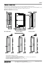
• Vertical Mounting
• Horizontal Mounting
50
40
30
20
10
0
-10
-20
-30
-40
-50
°C
%
100 SET
H
S
•
Z
L
90
80
70
60
50
40
30
20
10
0
SET (ENTER) Button
HH Setpoint Adj. & Trip Indicator (red)
H Setpoint Adj. & Trip Indicator (red)
Span Adj. (amber)
Power Saving Mode Indicator (amber)
Zero Adj. (amber)
L Setpoint Adj. & Trip Indicator (green)
LL Setpoint Adj. & Trip Indicator (green)
UP Button
Mode Selector
DOWN Button
HH Setpoint
H Setpoint
L Setpoint
LL Setpoint
PV Indicator
HH
LL
M
50
40
30
20
10
0
-10
-20
-30
-40
-50
°C
%
100
SET
LL
L
Z
•
S
90
80
70
60
50
40
30
20
10
0
H
HH
M
• Vertical Mounting
• Horizontal Mounting