14
Publication: ZTB-080112
M-B Companies, Inc. 11/14/12
iNTRODUcTiON
ADjUSTMENT AND SERvicE
ScRAPER hEighT ADjUSTMENT
The height of the scraper blade (cutting edge) will determine the quality
of snow removal. The scraper blade mounting position is fixed and
cannot be adjusted. The position of the skid shoes is adjusted vertically
to change the scraper blade clearance height.
If the skid shoes are positioned too far down, the scraper blade will not
clear all the snow. If skid shoes are set too high, the scraper blade will
wear and allow the ribbon (auger) to make contact with the ground.
Mismatched skid shoe heights will cause uneaven clearing of snow.
WARNiNg!
When making repairs or
adjustments, the tractor engine
must be Off if the snowblower is
connected.
1.
Park the tractor with the mounted snowblower on a hard, flat,
level surface; preferably concrete or asphalt.
2. Raise snowblower high enough to allow placement of shims
listed in step 3.
If using the snowblower on gravel or uneven surfaces, a
minimum gap of 1" (25 mm) is recommended to minimize the
scraping of unwanted debris. This will help avoid running gravel
through the snowblower. Allow 1/8" (3 mm) between scraper
blade and hard, smooth surfaces. Use appropriate shims when
adjusting height.
3. Place shims between scraper blade and hard, smooth ground
surface.
4. Lower snowblower onto ground/shims.
5. Shut off the tractor. Remove key from ignition and apply parking
brake.
6. Loosen the two lock nuts and carriage bolts for mounting each
skid shoe.
7. Push the skid shoes downward to make solid contact with the
ground. Tighten all mounting locknuts and bolts.
8. Remove shims from below scraper blade.
9. With the skid shoes on the ground, check the clearance
between scraper blade and ground surface. The ribbon must not
be in contact with ground.
NOTE:
If the skid shoes are wearing unevenly they can be
switched to the opposite side. When the skid shoes are
worn out they must be replaced.
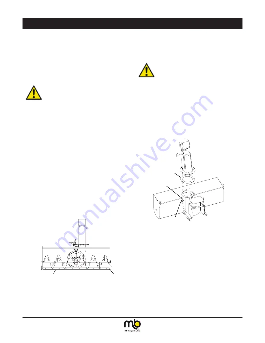
Place shims between the
ground and the scraper blade.
Skid Shoe
Figure 15
DiSchARgE chUTE gLiDE RiNg
The glide ring provides a sliding surface for the discharge chute
rotation. To clean and lubricate or replace the glide ring, the discharge
chute must be removed.
WARNiNg!
When making repairs or
adjustments on the snowblower,
the tractor engine must be off if the
snowblower is connected.
1. Support the discharge chute. Remove the nuts from all four of
the poly slide hold downs. The poly slides should be removed
and cleaned.
2. Lift the discharge up to remove the glide ring.
3. Clean or replace the glide ring. When reinsalling the glide ring
the bottom side should be lubricated with a spray grease.
4. Place the discharge chute in posiiton. Line up the carriage bolts
with the glide ring and the teeth in the plate with the rotation
drive gear.
5. Place the upper and lower poly slide pieces in place and secure
with a washer and locking nut.
6. Tighten the nuts so the chute rotates smoothly and is not a
loose fit.
Remove Nuts
Glide Ring
Poly Slides
Figure 16
Summary of Contents for ZTB
Page 2: ......


