12
Analog and Digital Inputs
To the right of the software returns section on the mixer page are the ProjectMix I/O analog and digital inputs. Analog inputs are labeled with
the prefix "ana," for example ana 1/2 in, ana 3/4 in, etc. Digital inputs are labeled with the "adt" prefix for ADAT lightpipe inputs, or "spdif" for
the S/PDIF inputs. As with the software return channels, you will find output select buttons at the bottom of each input channel.
The mixer page is dynamic, meaning it will change based on the inputs selected on the hardware page. For example, if you have chosen
adat input, the four ADAT inputs will appear to the right of the analog inputs; if you have chosen spdif input, the S/PDIF input will appear there
instead. (You may have to scroll to the right using the scroll bar on the bottom of the window if you do not see all the inputs.)
In addition to output routing selection, you may solo or mute any particular input channel with the corresponding button. You may also adjust
the volume of each channel independently, or link stereo pairs using the LINK button. NOTE: Any adjustments made to the controls on an
input channel will have no effect on the audio being recorded to the computer. These controls only adjust the monitoring of the signals at the
various outputs.
Below the software returns channels are miniature meters for the output buses. These mirror the levels on the output page.
Output Page
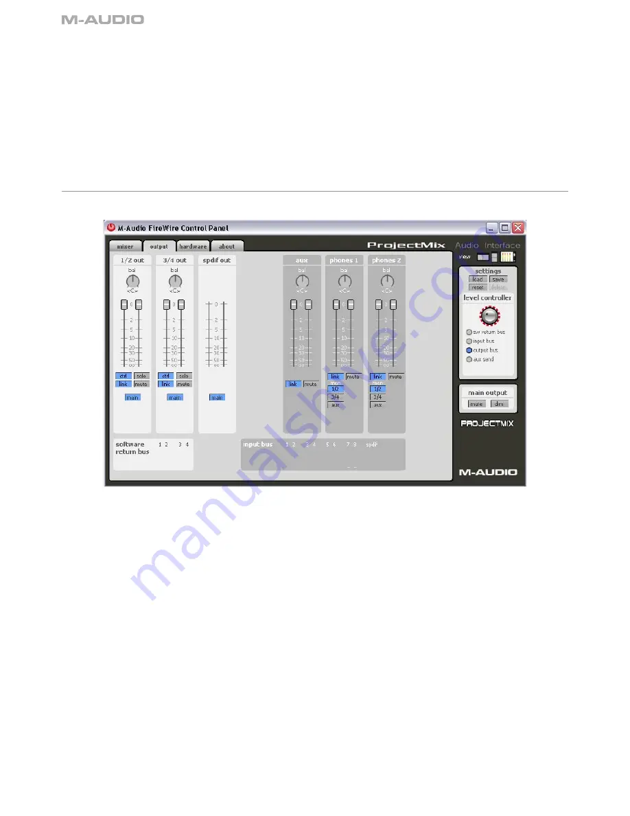
The output page is arranged much like the mixer page (click the output tab to open this page). Here you assign the audio output streams to
the ProjectMix I/O four analog outputs, or ADAT digital outputs, as well as regulate the output level of the aux bus and control the headphone
outputs.
Analog Outputs
The first two columns in the output page are 1/2 out and 3/4 out, which refer to the four 1⁄4" TRS outputs on the back of the ProjectMix I/O.
The bal knobs at the top of these channels are used to adjust the left/right balance (default is center). Below each bal knob is a pair of output
volume controls. By default, the link button is active, so moving one of the volume controls will cause the other to match it. If you want to adjust
them separately, click on the link button to turn it off.
You'll also find a mute button which will silence the output when active. The solo button does the opposite by muting all the other outputs.
Of special interest here is the main button. Clicking this button will make it change to aux (click again to go back to main). This button selects
which bus to use for the output. When set to main, the output channel will use its default bus. Mixer channels assigned to 1/2 will be heard
from LINE OUT jacks 1 and 2; mixer channels assigned to 3/4 will be heard from LINE OUT jacks 3 and 4. When either output is set to aux,
you'll hear the signals routed to the aux bus from these outputs instead.
Aux Channel
The aux output channel contains controls for adjusting the aux bus, such as balance and volume, before it is sent to an output. You probably
won't have to use this too often, but adjusting the volume here for example allows you to match levels when you're switching back and forth
between the aux bus and main outputs with the A/B button.
Headphone Outputs
The two controls to the right of aux are for assigning audio to the two headphone outputs. By default, both headphone outputs are assigned
to use the 1/2 bus as their source. Therefore, anything you hear on LINE OUTs 1 and 2 can also be heard on the headphones.
The Control Panel


