13.
Reset, press this button for about 2 second, then it will delete all the camera preset, please
use it carefully.
14.
Video-home, the video image will back to the video-home position when all mic off.
Connecting and operation instruction for camera central processor
1.
Connect the data port in conference main unit to the data port in this unit with data cable
2.
Connect the RS-232 port to the computer with computer cable
3.
Install the software to the computer(optional)
4.
Connect the high speed dome date cable to the dome port in this unit (if has many unit for
using, please use the multiple connecting), connect the high speed dome video cable
(within 8 sets) in to each input in the board behind the central processor (V1, V2, V3, V4,
V5, V6, V7, V8), the camera ID should be same as the video in port, it must configure
another distributor machine if over 8 sets, the high speed dome connect to the video
distributor
5.
After confirmed the conference system is adjusted to normal, open the conference system
and this main unit, computer software; camera function setting and testing according to the
software instruction.
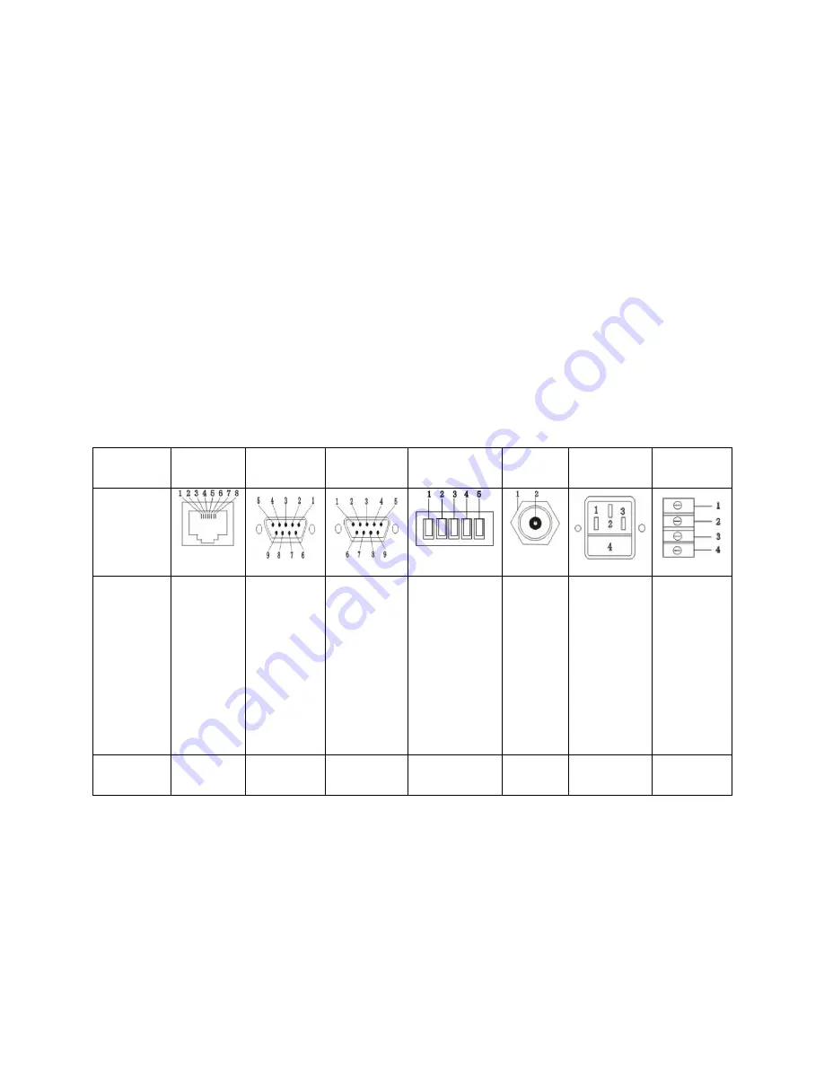
Port Schematic diagram
Name
RJ45
DB9
Female
DB9
Male
RS485/RS422
BNC
Power
Data
Pic
Description
1.GND
2.GND
3.RS485A
+
4.RS485B-
5.NC
6.NC
7.GND
8.GND
1.NC
2.TXD
3.RXD
4.NC
5.GND
6.NC
7.NC
8.NC
9.NC
1.NC
2.RXD
3.TXD
4.NC
5.GND
6.NC
7.NC
8.NC
9.NC
1.RS485 A+
(TXD +)
2. RS485 B-
(TXD -)
3. RXD +
4. RXD –
5. GND
1.GND
2.VIDEO
1.POWER
2.GND
3.POWER
4.FUSE
1.RS485B-
2.
3.AC24V
4.AC24V
Port name
DATA
RS232
DOME
(VISCA)
DOME
(PELCO-D)
INPUT/
OUTPUT
220V
POWER
DOME
DATA PORT
Summary of Contents for H-8000
Page 1: ...CONFERENCE VIDEO PROCESSOR H 8008 INSTRUCTION MANUAL ...
Page 5: ......
Page 6: ...System connection ...


