background image

Installation, Troubleshooting and Maintenance 

Installation
Piping

Whenever possible ensure the pump is installed using the 

shortest possible pipe lengths with the minimum amount of 

pipe fittings. Ensure all piping is supported independent of 

the pump.
Suction and discharge piping should not be smaller than the 

connection size of the pump. When pumping liquids of high 

viscosity, larger piping may be used, in order to reduce fric-

tional pipe loss.

Employ flexible hoses in order to eliminate the vibration 

caused by the pump. Mounting feet can also be used to re-

duce vibration effects. 
All hoses should be reinforced, non-collapsible and be capa-

ble of high vacuum service. Ensure that all piping and hoses 

are chemically compatible with the process and cleaning 

fluid.

For processes where pulsation effects should be  

reduced, employ a pulsation dampener on the discharge side 

of the pump. 
For self-priming applications, ensure all connections are air-

tight and the application is within the pumps dry-lift capabil-

ity. Refer to product specifications for further details.
For flooded suction applications, install a gate valve on the 

suction piping in order to facilitate service. 

For unattended flooded suction operation, it is recommended 

to pipe the exhaust air above the liquid source. In the event 

of a diaphragm failure this will reduce or eliminate the pos-

sibility of liquid discharging through the exhaust onto the 

ground.

Location

Ensure that the pump is installed in an accessible location, in 

order to facilitate future service and maintenance. 

Air

Ensure that the air supply is sufficient for the 


volume of air required by the pump. Refer to product specifi

-

cations for further details. For reliable operation, install a 5 

micron air filter, air-valve and pressure regulator. Do not ex

-

ceed the pumps maximum operating pressure of 120 psig.

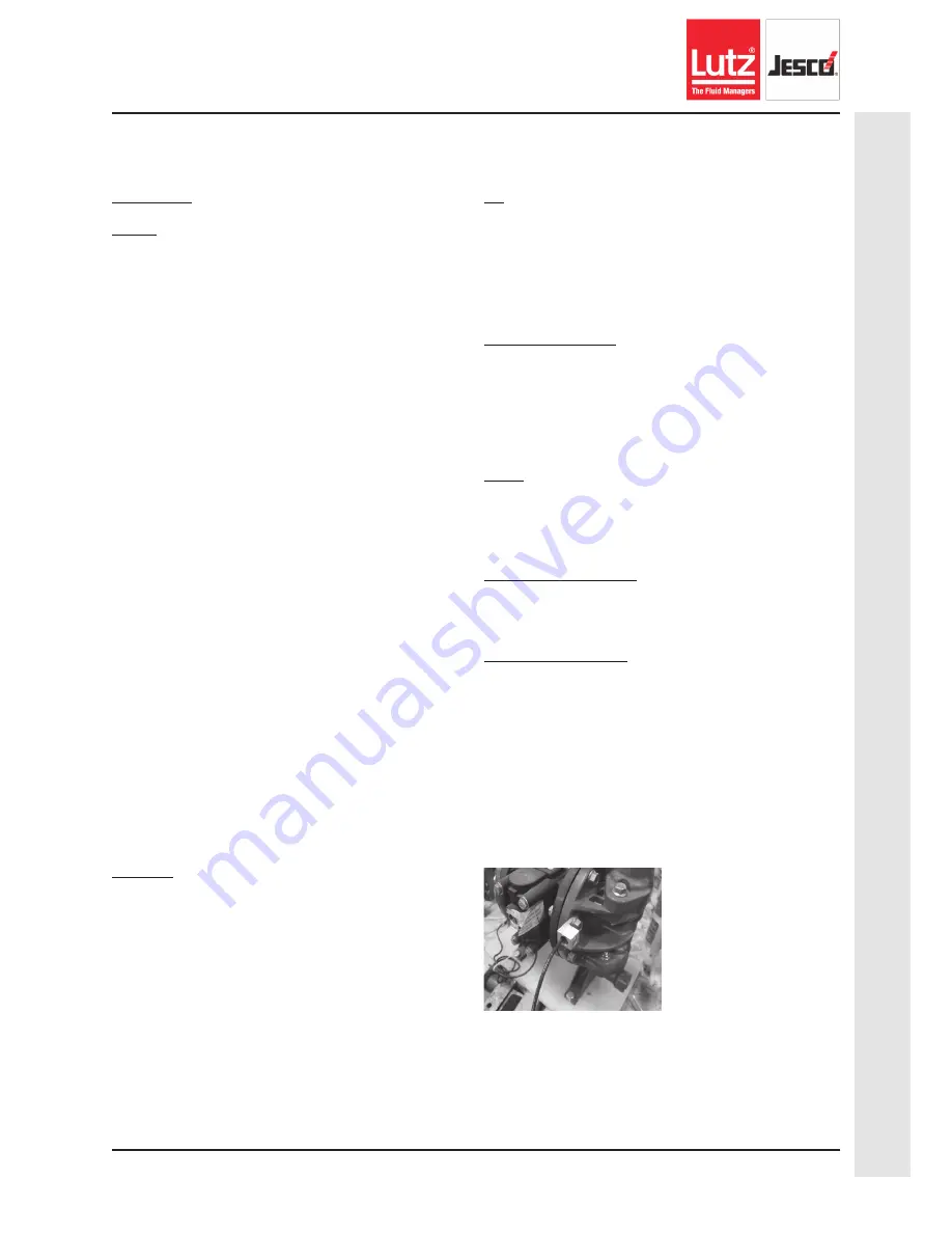
Remote Operation 

Utilize a three way solenoid valve for remote operation. This 

ensures that air between the solenoid and the pump is al-

lowed to “bleed off,” ensuring reliable operation. Liquid 

transfer volume is estimated by multiplying displacement per 

stroke times the number of strokes per minute.

Noise

Correct installation of the muffler reduces sound 


levels. Refer to product specifications for 


further details.

Submerged Operation

For submersible operation, pipe the air exhaust to atmo-

sphere

Grounding the Pump

Loosen grounding screw and install a grounding wire. Tighten 

grounding screw. Wire size should be a 12 gauge wire or larg-

er. Connect the other end of the wire to a true earth ground. 

Equipment must be grounded to achieve ATEX rating and it 

is recommended to configure the pump with a grounding lug 

option.

P h o n e :   ( 5 8 5 )   4 2 6 - 0 9 9 0  

 www.lutzjescoamerica.com


 Fax: (585) 426-4025

9

Operation & Maint

enance Ins

tructions 


AODD: 2” Air Operat

ed Double Diaphragm Pum

p

Summary of Contents for AIRTRAN LI20-FP Series

Page 1: ...A measured step forward TM AIRTRAN 2 Air Operated Double Diaphragm Pump...

Page 2: ...THIS PAGE INTENTIONALLY LEFT BLANK P h o n e 5 8 5 4 2 6 0 9 9 0 www lutzjescoamerica com Fax 585 426 4025 2 Operation Maintenance Instructions AODD 2 Air Operated Double Diaphragm Pump...

Page 3: ...12 Repair and Assembly 13 Pump Wet End Removal 13 Pump Wet End Assembly 14 Repair and Assembly 15 Air Valve Removal 15 Air Valve Assembly 16 Repair and Assembly 17 Pilot Valve Removal 17 Torque Specif...

Page 4: ...y the materials in contact with the fluid being pumped Consult a chemical resistance guide for chemical compatibility and a more precise safe temperature limit Always use minimum air pressure when pum...

Page 5: ...ler Grounding Lug Installed Note Equipment must be grounded to acheive ATEX rating It is recommended to configure the pump with a grounding lug option for ATEX applications SPECIAL OPTION OTHER 0 Stan...

Page 6: ...e outward to the left Since both the left diaphragm and the right diaphragm are connected via a dia phragm rod when the left diaphragm moves to the left the right diaphragm through the action of the d...

Page 7: ...6 446 31 7 805 13 7 349 12 2 310 1 9 49 7 6 194 6 0 153 4 0 101 14 2 360 16 7 423 0 6 14 8 2 208 9 2 234 Dimensions in inches mm P h o n e 5 8 5 4 2 6 0 9 9 0 www lutzjescoamerica com Fax 585 426 402...

Page 8: ...O Weight Polypropylene 56 lbs 25 kg Weight PVDF 84 lbs 38 kg Air Inlet 3 4 FNPT Liquid Inlet 2 ANSI DIN FLANGE Liquid Outlet 2 ANSI DIN FLANGE Height 31 7 805 mm Width 23 6 600 mm Depth 12 2 310 mm 0...

Page 9: ...ragm failure this will reduce or eliminate the pos sibility of liquid discharging through the exhaust onto the ground Location Ensure that the pump is installed in an accessible location in order to f...

Page 10: ...ustration is a generic representation of an air operated double diaphragm pump P h o n e 5 8 5 4 2 6 0 9 9 0 www lutzjescoamerica com Fax 585 426 4025 10 Operation Maintenance Instructions AODD 2 Air...

Page 11: ...essive Debris stuck in valves Excessive wear of check valves Air leak on suction side with suction lift Pump Cycles with Closed Discharge Valve Debris stuck in check valve Excessive wear of check valv...

Page 12: ...partially closing a liquid suction valve restrict the suction line and may cause damage to the diaphragms Suction strainers may be employed to reduce or eliminate larger solids but routine maintenance...

Page 13: ...ight Hex Head Cap Screws and Lock Washers sixteen Washers and eight Hex Nuts from the Dishcharge Manifold STEP 2 Remove the Discharge Manifold STEP 3 Remove the O Ring Valve Seat and Ball from the Dis...

Page 14: ...ower four bolts are inserted from the center STEP 8 Remove both Outer Chambers and Power Rings from the Intermediate Note the Lock Washers are installed on the Power Rings which should be on the Inter...

Page 15: ...ash ers Flat Washers and Hex Nuts rear STEP 2 Remove the main Air Valve Assembly from the pump STEP 3 Remove the Air Valve Gasket from the main Air Valve Assembly STEP 4 Remove the Shuttle Plate from...

Page 16: ...ly they will be unable to rotate Insert the spool larger chamber side first the spool s longer piston with the boss is to be on the plug side ensure O Ring is installed and then the air valve end plug...

Page 17: ...ure that the air and fluid lines are closed and disconnected While wearing personal protective equipment flush and drain process liquid from the pump WARNING Maintenance must not be performed when a h...

Page 18: ...rdering information Torque Specification Chart RECOMMENDED TORQUE SPECIFICATIONS 2 Pumps Chamber Bolts 20 ft lbs 27 1 N m Air Valve Bolts 40 in lbs 4 52 N m Diaphragm Plates 372 in lbs 42 0 N m Manifo...

Page 19: ...352 351 10 354 361 362 20 30 40 61 62 70 80 90 100 110 120 130 140 150 160 170 180 220 230 240 250 260 270 280 290 300 311 312 320 210 50 372 190 P h o n e 5 8 5 4 2 6 0 9 9 0 www lutzjescoamerica com...

Page 20: ...ypropylene 110 Pilot Sleeve 4 ALL MODELS 11919 16 Urethane 120 END SPACER Pilot Sleeve 2 ALL MODELS 10206 40 Polypropylene 130 O RING End Spacer 2 ALL MODELS 11919 11 Nitrile 140 LIP SEAL Diaphragm Ro...

Page 21: ...HEX 1 2 13 36 ALL MODELS NON PTFE COATED 12604 26 Stainless Steel 371 WASHER LOCK 1 4 6 ALL MODELS NON PTFE COATED 12350 26 Stainless Steel 372 WASHER SPLIT LOCK 1 4 36 ALL MODELS NON PTFE COATED 123...

Page 22: ...r to EPDM Has excellent abrasion resistance Temperature range 40 F to 225 F 40C to 107C FKM is an elastomer with good corrosion resistance to a wide variety of chemicals Similar in chemical resistance...

Page 23: ...THIS PAGE INTENTIONALLY LEFT BLANK P h o n e 5 8 5 4 2 6 0 9 9 0 www lutzjescoamerica com Fax 585 426 4025 23 Operation Maintenance Instructions AODD 2 Air Operated Double Diaphragm Pump...

Page 24: ...complete chemical feed system we provide you with the appro priate Total Fluid Management solution Please contact us for more information Lutz JESCO Corp 55 Bermar Park Rochester NY 14624 Phone 585 42...

Reviews: