background image

®

Wallbox Power Module Installation and Operation Guide   9

OK

1

2

3

4

5

6

9

10

11

12

13

14

7

8

15

16

9-16

1-8

OK

1

2

3

4

5

6

9

10

11

12

13

14

7

8

15

16

9-16

1-8

DALI Setup

Assigning/Unassigning a DALI Device to a Zone

DALI devices must be addressed on the system (see previous page) before assigning 
or unassigning to a zone.

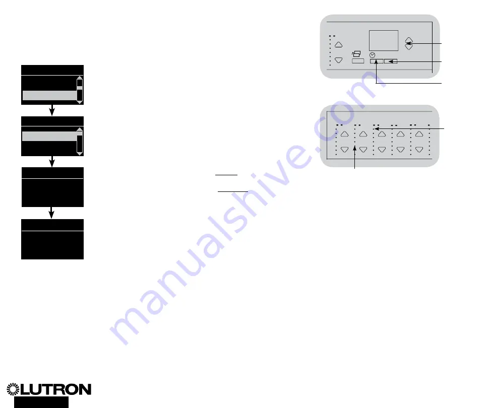
1.  Enter programming mode.
2.  Use the Master buttons to highlight “DALI” and press the OK 

button to accept.

3.  Use the Master buttons to highlight “Assign zones” and press 

the OK button to accept.

4.  Use the Master buttons to scroll through the DALI devices on 

the link. The selected device will flash, and the info screen 

will display the device number and the number of devices on 

the link. If the device is currently assigned to a zone, the zone 

number will display at the bottom of the screen and the LEDs 

for the zone will go on; otherwise, the info screen will display 

“*Unassigned*”. 

   •  Press the zone raise button to assign the device to that 

zone.

   •  Press the zone lower button to unassign the device to that 

zone.

5.   Press the Timeclock (back) button to return to the DALI menu. 

DALI devices will return to normal levels.

6.  Exit programming mode. 

 Notes

•  

Devices that were previously assigned to a zone will be 

removed from the old zone and assigned to the new zone 

(each device can be assigned to only 1 zone at a time). 

•  Devices can be assigned only to zones set to DALI


load type.

•  

Refer to the Zone Setup section for instructions on changing 

load type.

Use the 

zone raise 

or lower 

button to 

assign or 

unassign a 

DALI device 

to that 

zone.

Zone LEDs

Main menu

Zone setup

Zone setup

DALI

Address All

Assign zones

Assign zones

Ballast 2 / 23

Zone 3

DALI

Assign zones

Ballast 2 / 23

*Unassigned*

Master 

buttons

OK  

button

Timeclock 

(back) button

Summary of Contents for LQR-WPM-16D

Page 1: ...mbers Ratings 120 240 V 50 60 Hz 100 mA 230 V 50 60 Hz 100 mA Typical Power Consumption 7 W 24 BTUs Power Draw Units PDUs 0 Output DALI Link 18 V 250 mA Codes Install in accordance with all applicable...

Page 2: ...age terminal can accept one 4 0 mm2 wire Consult Lutron for non dim relay wiring and or load side emergency transfer wiring D1 D1 D2 D2 1 2 3 4 5 6 L N 1 2 3 4 5 6 L N Wiring the Wallbox Power Module...

Page 3: ...WARNING Shock hazard May result in serious injury or death Always turn off circuit breaker or remove main fuse from power line before doing any work Step 3 Connect line voltage and loads to control u...

Page 4: ...e live Always turn off circuit breaker or remove main fuse from power line before wiring and servicing the Wallbox Power Module Step 1 Use the wire size chart at right to determine which wire size to...

Page 5: ...use from power line before doing any work Step 1 Strip 25 mm of insulation from the IEC PELV NECR Class 2 cable Step 2 Strip 7 mm of insulation from each wire in the cable Step 3 Connect the wires to...

Page 6: ...e on rest the top of the wallplate in the grooves at the top of the unit and press firmly at the bottom corners to secure Step 4 Turn on circuit breaker and check that it does not trip For any feed ci...

Page 7: ...ou to move through the menu choices The current choice is highlighted on the info screen OK Button The OK button chooses the current highlighted menu choice This will either take you to the next menu...

Page 8: ...tton to erase all current programming reset and address DALI devices and find sensors on the system 5 Exit programming mode Note After running Build System Zone 4 will control all DALI devices for dia...

Page 9: ...display at the bottom of the screen and the LEDs for the zone will go on otherwise the info screen will display Unassigned Press the zone raise button to assign the device to that zone Press the zone...

Page 10: ...he OK button to accept 3 Use the Master buttons to highlight Address All and press the OK button to accept All DALI devices in the system will go to full On As each DALI device is addressed the Wallbo...

Page 11: ...the third tap Step 2 Keep the Default Scene Button pressed on the third tap for approximately 3 seconds until the LED flashes slowly Step 3 Release the Default Scene Button and immediately triple tap...

Page 12: ...and shorts HomeWorksR QS only Device is in the Factory Default Settings mode and has not been activated into the system Use the system software to verify activation or reactivate the device and transf...

Reviews: