


Wallbox Power Module Installation and Operation Guide 8
®
DALI Setup
After DALI
devices are wired and powered, they must be addressed before the
system can control them. The “Build System” command automates this process.
Note:
All existing DALI
programming will be deleted when the “Build System”
command is run, including DALI
sensor programming on the Wallbox Power
Module control unit.
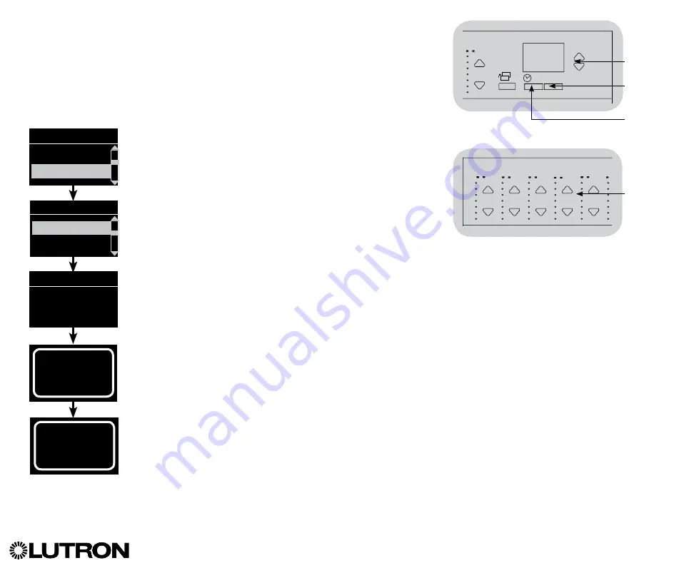
Building the System
1. Enter programming mode by pressing and holding the OK
button and timeclock (back) button for 3 seconds.
2. Use the Master buttons to highlight “DALI” and press the OK
button to accept.
3. Use the Master buttons to highlight “Build system” and press
the OK button to accept.
4. Press the OK button to erase all current programming, reset
and address DALI devices, and find sensors on the system.
5. Exit programming mode.
Note:
After running “Build System”, Zone 4 will control all DALI
devices for diagnostics and verification of wiring. (This
feature is disabled once any of the addressed devices
are assigned to a zone on the Wallbox Power Module
control unit.) Use the Zone 4 raise/lower buttons to verify
that all devices are correctly addressed. If a device does
not respond, repeat the “Build System” command and/
or check the wiring.
Main menu
Zone setup
DALI
Assign zones
Build system
Erase digital load
Programming?
Build system
DALI
OK
1
2
3
4
5
6
9
10
11
12
13
14
7
8
15
16
9-16
1-8
Use Zone 4
raise/lower
buttons
to verify
all DALI
devices
have been
addressed.
Searching...
x
Found
x Loads
Found
OK
1
2
3
4
5
6
9
10
11
12
13
14
7
8
15
16
9-16
1-8
Master
buttons
OK
button
Timeclock
(back) button