English
Español
Français
Português
2
Installation
4. Connect to HomeWorks lighting controls.
For the
H4P5-H48-120 and H4P5-H48-HRL-120 models only,
connect the communication wiring from the
HomeWorks
Maestro
®
Dimmers to the factory installed Dimmer Hub
(HWI-H48-120). See Figure 4, page 3. Connect the
buses according to the bus assignments that were made
using the
HomeWorks Illumination
Software. Gray and
violet connections are marked on the printed circuit
board.
5. Connect Dimmer Hub links:
For the H4P5-H48-120 and
H4P5-H48-HRL-120 models only, an internal harness
connects Link 4 to the factory installed Dimmer Hub. If
additional HWI-H48 or HWI-Q96 boards are to be con-
trolled by the processor, the communication link to those
boards should be connected into the Link 4 terminal
block. Do not connect terminal 2 to an HWI-H48/Q96. If
the H48/Q96 Link has a cable length of 50 feet (15 m) or
more, LT-1 link terminators must be installed across
MUX and MUX (terminals 3 and 4) at both ends of the
link. Refer to HWI-H48 instructions (see also Figure 5,
page 4).
Note -
Links 4, 5 and 6 are configurable for use
as Keypad Links, GRAFIK Eye
®
Links, or
H48/Q96 Links. These links are configured by the
HomeWorks Illumination
Software.
6. Connect Inter-processor Link (multiple processor
installations only):
The Inter-processor Link is used for
communication between
HomeWorks
Processors.
Connect control wiring to the Inter-processor Link (Link
2), if required. Do not connect terminal 2 (see Figure 5,
page 4). If this processor is to be the first or last
processor in the daisy chain, attach one of the LT-1 link
terminators provided across the MUX and MUX (termi-
nals 3 and 4—see Figure 5, page 3). If LT-1 terminators
are unavailable, a 1/2 W resistor between 100 and 150
Ohms may be placed across terminals 3 and 4 to provide
termination.
7. Connect GRAFIK Eye / WPM links
: If
GRAFIK Eye
preset dimming controls or Wallbox Power Modules are
to be controlled by this processor, connect the communi-
cation wires to Link(s) 4, 5, or 6 as configured in the
HomeWorks Illumination
Software. Do not connect
terminal 2.
8. Connect Keypad links:
For keypads or keypad link
devices (e.g. HWI-CCO-8) that are to be controlled by
this Processor, connect the communication wires to
Link(s) 4, 5, or 6 as configured in the
HomeWorks
Illumination
Software.
Note:
Connecting keypads or
keypad link devices to links other than Link 6 requires an
additional power supply.
9. Connect Hybrid Repeater link:
For the H4P5-H48-HRL-
120 and H4P5-HRL-120 models only, connect the Hybrid
Repeater communication wires to Link 8. Note: DO NOT
connect the +15 V terminal (terminal 2) if the Hybrid
Repeater(s) will be powered by the plug-in 9 V
adapter
provided with the repeater(s).
10.Connect power.
Plug the power input harness terminals
(blue wires) from the HWI-LV24 enclosure onto the
power feed lugs on the
4 Series
Processor. Connect plug
from adapter to Link 6/8 Power connector. Plug adapter
1.
Ensure High-voltage cover in HWI-LV24 enclosure is
securely installed. Locate and lock supply breaker in the
OFF position before installing processor assembly.
Danger -
Wiring with power on may result in
personal injury.
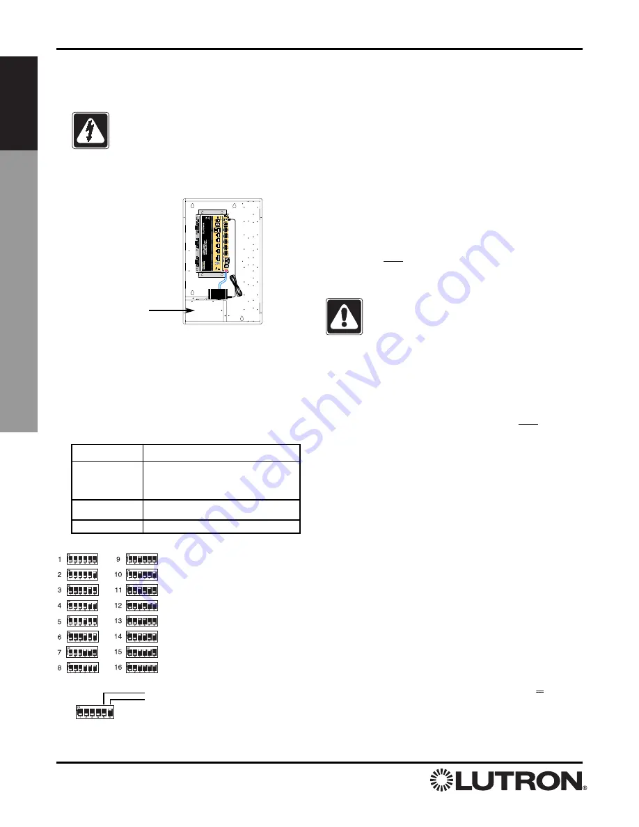
2. Install processor assembly in the enclosure:
The
HomeWorks
®
4 Series
TM
Processor is attached to the
HWI-LV24 enclosure using four mounting keyholes and
the mounting screws provided.
3. Set processor address.
Set processor address using
the Configuration Switch. The
HomeWorks
Illumination
TM
Software will prompt the programmer if any subsequent
changes to the configuration switches are required (see
Table 2). The factory installed Dimmer Hub is already
addressed to “1”. (H4P5-H48-120, H4P5-H48-HRL-120)
Figure 2 - Mounting
Diagram
The
4 Series
Processor mounts
in the upper left corner of an
HWI-LV24 enclosure.
High-voltage enclosure
(shown with cover installed).
Figure 3 - Processor Addressing
DIP Switch
Function
1
Boot Mode. Unless prompted by the
HomeWorks Illumination
Software, this
switch should always be in the DOWN
position.
2
RS-232 Baud Rate: UP = 9600 Baud,
DOWN = User selected Baud.
3-6
Processor Address. See Figure 3, below.
Table 2 - Configuration Switch Functions
Down (OFF)
Up (ON)
Example: Setting Switch #6 ON.


