


14.0 REPLACEMENT OF THE WIRE SPOOL
The wire is pushed by a roll (FIG.4, M) which is moved by a series of
mechanisms. The roll has two grooves one marked by 0.6 mm and the
other marked by 0.8 mm. It is very important to use the correct groove as
explained in page 10 – “ PREPARATION FOR WELDING” – otherwise
the wire will not be fed regularly or it will be crashed; make sure that the
torch tip matches with the wire diameter. Your welding power source is
supplied with a torch complete of tip for the wire included with the power
source. For all the other wire spools mount a tip that matches with the wire
diameter.
Make reference to (Fig. 4) and follow the procedure described at page 4 –
“ INSTALLATION OF THE WELDING WIRE “ for the replacement of
the wire spool.
15.0 WELDING TIPS
1. Keep the torch handle with an angle of 45° with respect to the workpi-
ece and maintain the nozzle about 6mm from the surface.
2. Move the torch handle with prudence and steadiness.
3. Avoid welding in areas with too much air. The air that blows away the
shielding gas from the weld pool mainly causes porosity in the weld.
4. Keep the wire and its cover clean. Do not use rusted wire.
5. Avoid sharp bends and kinks on the welding hose.
6. If possible, clean with compressed air the wire liner when replacing the
wire spool.
7. Periodically remove the dust, using low pressure (3-4bar / 20-30 PSI)
from the inside of the power source, to assure adequate heat dissipation
from power source during operation.
16.0 ADJUSTMENT OF THE POWER SOURCE
“Stick out” (sometimes improperly called arc length) should remain in the
range 5mm ÷ 10 mm in order to obtain best welding (and sound) perfor-
mances.
1. Position the voltage switch in the desired position (TAB. 13.1, 13.2).
Select lower position for lower thickness and higher settings for higher
thickness.
2. Adjust the wire speed. Start using a trial metal sheet thoroughly clea-
ned from layers of rust or paint. Connect the ground cable to the work-
piece. Adjust the wire speed at high setting. Press the torch switch
(note: The torch switch must be pressed thoroughly in order to perform
its three functions, gas flow, wire feed and welding current). Start wel-
ding and decrease the wire speed gradually. Continue to decrease the
wire speed and listen to the sound. The sound will change from a crack-
ling noise to a regular and strong buzzing (similar to the sound of fry-
ing bacon). This buzzing sound indicates the correct wire speed for the
workpiece being welded. When the current regulation is changed set
again the wire speed.
Start always from a higher wire speed. This operation prevents from
damaging the contact tip during welding. During welding the torch
should be kept with the 45° angle from the workpiece. Keep the top of
the nozzle at 5-10mm from the work-piece.
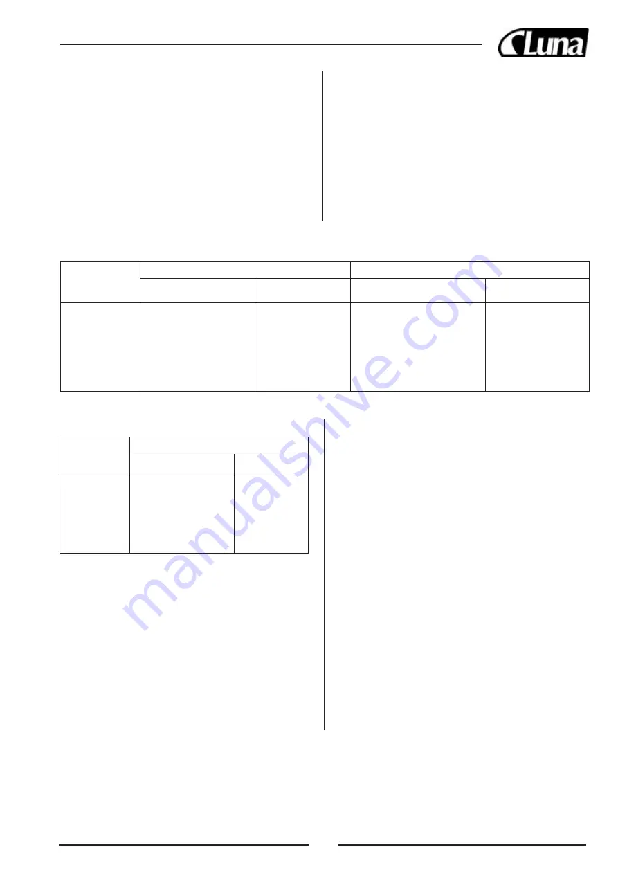
0,6 mm Gas Welding Wire
0,8 mm Gas WeldingWire
Workpiece
Welding Position
Wire Speed
Welding Position
Wire Speed
Thickness (mm)
Adjustment
Adjustment
A
B
C
D
A
B
C
D
0,6
1
2
Min.
Low
Professional welding
Low
0,6 - 0,8
1
2
Max.
Low
1
2
Max.
Low
0,8 - 1,0
A
2
Min.
Medium
A
2
Min.
Low
1,0 - 1,2
A
2
Max.
Medium
A
2
Max.
Medium
1,2 - 2,0
A
3
Min.
Medium
A
3
Min.
Medium
2,5 - 3,0
A
3
Max.
High
A
3
Max.
Medium
13.1 REGULATION REFERENCE TABLE
STEEL
0,9 mm Gas Welding Wire
Workpiece
Welding Position
Wire Speed
Thickness (mm)
Adjustment
A
B
C
D
0,9
1
2
Max.
Low
0,9 - 1,0
A
2
Min.
Medium
1,0 - 1,2
A
3
Max.
Medium
1,2 - 2,0
A
3
Min.
Medium
2,0 - 3,0
A
3
Max.
High
SOFT STEEL FOR NO GAS
21
11.0 NO GAS WELDING
In the “NO GAS welding” the torch is connected to the negative pole (-)
and the ground cable to the positive pole (+). By gas welding the shielding
gas is used to protect the weld pool from oxidation and porosity. By NO
GAS welding this protection is given by a special wire called “flux cored
wire”, this technique simplifies the use of these machines compared to the
machines with standard wire, on which the gas flow must be adjusted sepa-
rately.
12.0 ADVANTAGES OF NO GAS WELDING
1. There is no need for gas cylinders.
2. Welding outdoors is easier because there are fewer chances that wind
blows away the shielding gas.
3. Welding time is about 50% less compared to the normal electrode wel-
ding.
4. The learning time for the operator is very short.
5. Minimum waste of welding material.
6. Most important, this process allows to complete the welding more
quickly and efficiently.
7. Less heat, less distortion.
8. Possibility to weld thin materials.
13.0 WELDING PROCEDURES
1. Your welding power source has six positions for the regulation of the
current in the various conditions.
2. The choice of the position for the welding is determined by the thick-
ness of the material to weld.
3. Also the gas flow rate is determined by the thickness of the material to
weld.
4. For the adjustment of the power source make reference to the graphs
and of the following pages.
Summary of Contents for WM 1605 F
Page 1: ...20421 0090 Gas no gas MIG welding units Svets med gas utan gas WM 1605 F...
Page 45: ...44 1 7 2 0 2 1 0 40 C 300 2 2 2 3 1 230 1 7 S E L 3 0 2 3 1 2 2 A 3 B 3 2 EURO 3 4 0 8...
Page 49: ...48 17 0...
Page 55: ...54...
Page 56: ...55...
Page 57: ...56...