


20
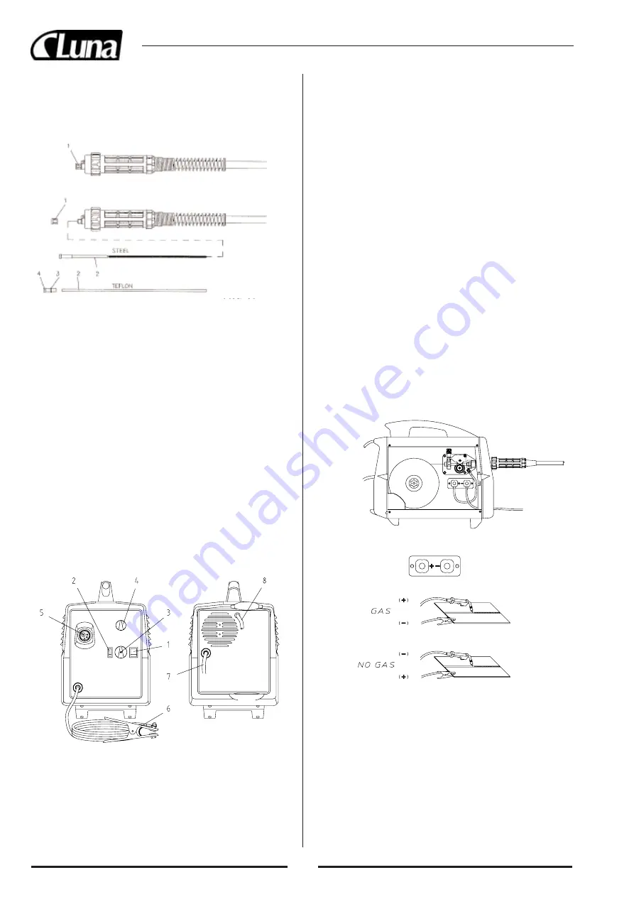
1) Main ON/OFF switch (fig. 6)
This yellow switch functions also as overtemperature pilot lamp; it will
light up if the thermostatic protection will cut off the machine and will
automatically extinguish after the machine has cooled sufficiently.
2) Min/Max switch
3) Voltage selector commutator
It is a 3 position rotary switch. With this switch you can adjust the welding
voltage according to the wire feed speed and wire diameter. The 3 position
rotary switch is completed by a Min/Max switch. Through the different
combinations you can obtain 6 voltage levels.
4) Wire speed adjustment knob
To increase the wire speed, turn the potentiometer clockwise; to decrease
the wire speed, turn it counter-clockwise.
5) Torch connection
6) Ground cable
7) supply cable
8) Gas hose
8.0 MIG WELDING
In MIG welding (Metal Inert Gas) a continuously fed metal electrode is
melted into a welding pool at constant and controlled speed. The wire is
connected to a constant voltage pole while the workpiece is connected to
the other pole. When the wire is fed and touches the workpiece, an electric
arc is produced. The arc melts the wire that is deposited on the workpiece
9.0 GAS WELDING
In order to weld Stainless steel or Aluminium the power source must be
set for gas welding *.
This operation is very simple, you only need the following spare parts
and items (please contact your welding supplier):
1. Wire – All these power sources work with 5Kg-wire spools (wire dia-
meter 0.6mm or 0.8mm).
2. Tip – The tip is correct when it matches with the wire diameter. (Note:
when using aluminium wire of diameter 0.8mm the tip must be
1.0mm)
3. Gas – You can buy disposable gas cylinders from the local distributor
or from a reseller of spare parts, while rechargeable gas cylinders can
be supplied by the local re-seller of spare parts.
4. Gas regulators – You can buy the regulator suited for the gas cylinder
from the local distributor or from a re-seller of spare parts for welding
equipment. Note: As first thing you should decide if you want to use
rechargeable or disposable gas cylinders because this will affect the
choice of the regulator
10.0 WELDING PREPARATION
Fig. 5
motor at variable speed must slide through the liner; when it exits from
the torch neck, release the torch switch, turn off the machine and mount
the contact tip and the nozzle.
6.0 RENEWING THE WIRE LINER
Before performing this procedure, ensure the gas and electrical supplies
are disconnected. (fig. 5).
Euro Connection:
Fig.7
Fig.8
• Disconnect the torch from the machine.
• Place it on a flat surface and carefully remove the brass nut (1) (fig. 5).
• Pull the liner out of the hose.
• Install the new liner and mount the brass nut (1) again.
• In case you are replacing a Teflon wire liner, follow these instructions:
• Install the new liner and take care to insert also the O-ring (3) on the wire
liner collet (4).
• Install the collet on the wire liner and replace the brass nut (1).
• Cut the wire liner close to the brass nut.
WARNING: the length of the new wire liner must be the same of the
liner you have just pulled out of the hose.
• Connect the torch to the machine and install the wire into the feeding
system.
6.1 HOW TO CHOOSE THE WIRE LINER FOR EURO
CONNECTION TORCHES.
Mainly we can have 2 types of wire liners: Steel wire liners and Teflon wire
liners.
• The steel wire liners can be coated or not coated: the coated wire liners
are used for air cooled torches; the wire liners which are not coated are
used for water cooled torches.
• The Teflon wire liners are suggested for the welding of Aluminium, as
they allow a smooth feeding of the wire.
Colour
BLUE
RED
YELLOW
Diameter
Ø 0,6-0,9
Ø 1,0-1,2
Ø 1,2-1,6
7.0 WELDERS CONTROL
1. Connect the welding machine to the 230V 50/60Hz line;
2.
IMPORTANT:
make sure that the polarity is correctly set. For GAS
welding the ground cable must be connected to the negative pole (-),
while the torch must be connected to the positive pole (+) (fig. 7).
3. Connect the ground clamp to the workpiece and make sure that the con-
tact is good;
4. Make sure that the wire-feeding roll is correctly positioned (groove mat-
ching the wire diameter). In order to change the groove loosen the knob
that locks the roll. Note that each roll has two grooves one marked by
0,6 mm and the other marked by 0,8 mm. Turn the roll and fix it again
with the screw;
5. Open the gas using the pressure regulator and adjust the flow rate.
(NOTE: The gas flow may need adjustments in order to obtain a better
welding, this depends on the type and thickness of the metal used, any-
way the gas flow should be maintained as low as possible).
Summary of Contents for WM 1605 F
Page 1: ...20421 0090 Gas no gas MIG welding units Svets med gas utan gas WM 1605 F...
Page 45: ...44 1 7 2 0 2 1 0 40 C 300 2 2 2 3 1 230 1 7 S E L 3 0 2 3 1 2 2 A 3 B 3 2 EURO 3 4 0 8...
Page 49: ...48 17 0...
Page 55: ...54...
Page 56: ...55...
Page 57: ...56...


