background image


Acuity LS 


 Page 5 

Operating Manual  #OMA20200327 


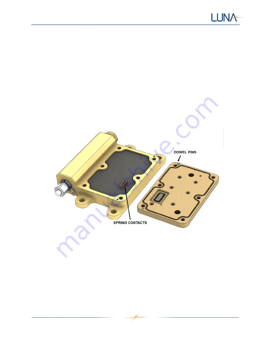
2.  Orient  the  LSP  so  that  its  two  metal  dowel  pins  align  with  the  mating  holes  in  the  Acuity  base 

(Figure 3).  

CAUTION:  Misalignment  or  using  the  wrong  orientation  of  the  LSP  could  result  in  bent  spring 
contacts and irreparable damage to the Acuity LS based and LSP. 

3.  Hold the LSP onto the base while reinstalling the six socket-head cap screws, applying only light 

torque until all screws are seated.  

CAUTION: Do not cross-thread or overtighten the screws, this could cause irreparable damage to 
the Acuity LS LSP.


4.  Using a torque-limiting driver, tighten all screws to 15 lbf-in [1.7 N-m]. 

5.  Verify  functionality  of  the  new  assembly 

using  the  Acuity  LS  Interface  software.    The  “System 

Check”  function  in  Section  5,  "Operating  the  User  Interface"  will  confirm  the  LSP  is  in  good 
contact by displaying reasonable measurements for air temperature and relative humidity. 

LSP installation is now complete. 


Figure 3.  

 Acuity LS base (left). Electrical spring contacts connecting base to LSP (right).   

NOTE: LSP O-ring seal not shown.  

LSP Surface Preparation for Testing 

The LSP is delivered in a clean condition ready for use.   

If the surface is contaminated, water rinsing can be done to the conductance, free corrosion, and galvanic 
corrosion sensors.  If organic contaminants need to be removed, wiping of the sensors with mild solvent 
(isopropyl alcohol) using a non-abrasive foam or cotton swab can be done.   

CAUTION:  Do  not  immerse  the  Acuity  LS  device  or  flood  the  filter  cap  area  that  houses  the 
relative humidity and temperature sensor with solvent, this could affect the temporary operation of 
these sensors or cause permanent damage. 

Summary of Contents for Acuity LS

Page 1: ...ACUITY CORROSION MANAGEMENT SOLUTIONS Acuity LSTM OPERATING MANUAL OMA20200327 sensinst lunainc com...

Page 2: ...ment 6 System Restart 7 4 Software and Driver Installation 7 Acuity LS User Interface Software and USB Driver Installation 7 5 Software Operation 8 Establishing Communication 8 Operating the User Inte...

Page 3: ...ble by the user Replacement Acuity LS Lid Sensor Panels LSP may be purchased from Luna 2 HARDWARE DEFINITION The Acuity LS system includes a multi sensor data acquisition device that saves data intern...

Page 4: ...LSP and base interface 2 Remove all socket head cap screws using 9 64 hex wrench Take care to avoid sideways motion of the LSP as the screws are removed as this may damage the internal spring pin conn...

Page 5: ...eck function in Section 5 Operating the User Interface will confirm the LSP is in good contact by displaying reasonable measurements for air temperature and relative humidity LSP installation is now c...

Page 6: ...ttery cap Figure 4 3 Remove the metal battery contact tube and the battery For sensors mounted with battery cap facing up the battery is more difficult to extract In these situations it may be possibl...

Page 7: ...tions for installing the software and drivers needed to communicate with Acuity LS Please ensure that your computer meets these basic system requirements Laptop or desktop computer with Windows 7 8 or...

Page 8: ...e computer 1 Remove the protective cap Figure 1 item 4 and install the RS 485 cable Figure 1 item 5 The other end of the cable plugs into any USB 2 0 compliant serial port NOTE When finished communica...

Page 9: ...port does not depend on which physical USB port is used Figure 6 Configuring the communications COM port 5 Select a COM port e g COM4 and click the OK button a If the correct COM port has been selecte...

Page 10: ...Displays the sampling interval in minutes currently set for the device Acuity LS Device ID Displays the serial number of the connected Acuity LS device This number should match the label on the outsi...

Page 11: ...connect a different Acuity LS device without restarting the interface utility software System Check Instructs the Acuity LS device to immediately take a set of measurements and display the results in...

Page 12: ...the provided text boxes The Aircraft Asset window can be used to enter specific information and notes about the aircraft asset or structure being monitored The Acuity LS device window can be used to e...

Page 13: ...to return to the main screen 8 Once data logging has started the System Status on main screen will indicate Logging Data and displays the selected Sampling Interval and Gold IDE Setup Download Data L...

Page 14: ...ce first sample in data file C Air Temp C Temperature of the ambient air in degrees Celsius D RH Percent relative humidity of the ambient air E Surface Temp C Temperature of the structure in degrees C...

Page 15: ...C 0 UNIX time may be readily converted to other time and date formats using the methods in Table 2 or this time converter https www epochconverter com Table 2 Converting UNIX time to other date and ti...

Page 16: ...nits Sensor Excitation Surface Temperature Ts 40 85 C DC current Air Temperature Ta 40 85 C Relative Humidity RH 0 100 Conductance Low Freq GH 0 005 1 S 20 mVpp 10 Hz Conductance High Freq GL 5 10 000...

Page 17: ...tem CD Compact Disk COM Communications FTDI Future Technology Devices International ID Identification IDE Interdigitated Electrode IPA Isopropyl Alcohol LSP Acuity LS Lid Sensor Panel PC Personal Comp...

Reviews: