Acuity LS
Page 5
Operating Manual #OMA20200327
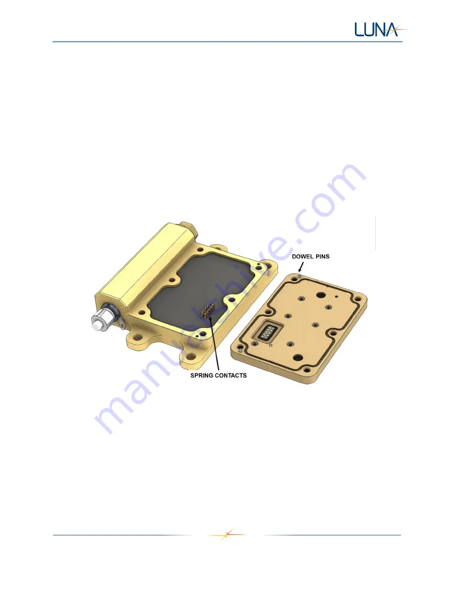
2. Orient the LSP so that its two metal dowel pins align with the mating holes in the Acuity base
CAUTION: Misalignment or using the wrong orientation of the LSP could result in bent spring
contacts and irreparable damage to the Acuity LS based and LSP.
3. Hold the LSP onto the base while reinstalling the six socket-head cap screws, applying only light
torque until all screws are seated.
CAUTION: Do not cross-thread or overtighten the screws, this could cause irreparable damage to
the Acuity LS LSP.
4. Using a torque-limiting driver, tighten all screws to 15 lbf-in [1.7 N-m].
5. Verify functionality of the new assembly
using the Acuity LS Interface software. The “System
Check” function in Section 5, "Operating the User Interface" will confirm the LSP is in good
contact by displaying reasonable measurements for air temperature and relative humidity.
LSP installation is now complete.
Figure 3.
Acuity LS base (left). Electrical spring contacts connecting base to LSP (right).
NOTE: LSP O-ring seal not shown.
LSP Surface Preparation for Testing
The LSP is delivered in a clean condition ready for use.
If the surface is contaminated, water rinsing can be done to the conductance, free corrosion, and galvanic
corrosion sensors. If organic contaminants need to be removed, wiping of the sensors with mild solvent
(isopropyl alcohol) using a non-abrasive foam or cotton swab can be done.
CAUTION: Do not immerse the Acuity LS device or flood the filter cap area that houses the
relative humidity and temperature sensor with solvent, this could affect the temporary operation of
these sensors or cause permanent damage.


