
60
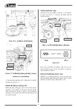
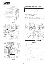
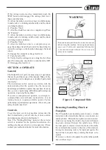
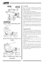
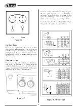
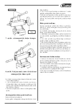
Figure9. Tailstock positioning controls.
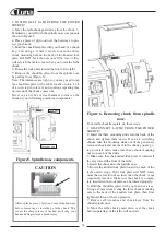
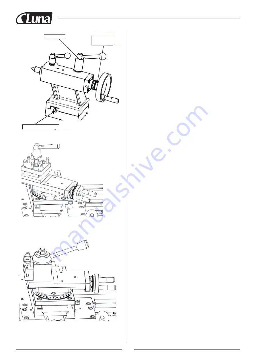
Figure10. Removing tool post lock
handle.
Figure11. Optional quick change tool
post installed.
Cross Slide
The cross slide moves perpendicular to the longitu-
dinal axis and features a scale on the hand wheel that
displays graduations of one thousandths of an inch
(0.001”) or 0.025mm.
To adjust the cross slide, do these steps:
1. Using the hand wheel, back the cross slide away
from your starting point by at least 0.015”, then move
the cross slide forward to your starting point. Note:
This procedure will clear any free movement (or
backlash) in the lead screw so your hand wheel scale
reading will be accurate.
2. Hold the hand wheel still and turn the scale so the
“0” mark lines up with the “0.000” mark on the cross
slide, as shown in Figure 12. As long as you avoid
backlash by continuing to move the cross slide in the
same direction, the scale on the hand wheel will be ac-
curate.
3. After backing the cross slide away from the Work
piece, remember to clear the backlash before moving
the cross slide forward to the “0” mark for the next
cut.
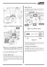
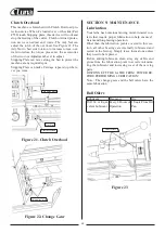
Compound Slide
Similar to the cross slide, the compound slide features
a scale that displays graduations of one thousandths of
an inch (0.001”) or 0.025mm. Unlike the cross slide,
the compound slide can be rotated to a set angle and
then it can be moved back and forth along the axis of
that angle.
To adjust the compound slide, do these steps:
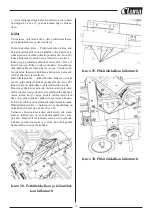
1. Loosen the compound bolts shown in Figure 13 to
allow it to be rotated.
2. Rotate the compound slide to the angle needed for
your procedure.
3. Tighten the compound slide bolts, and check the
angle again to make sure it did not move during tigh-
tening.
4. Use the compound slide hand wheel to move the
tool back and forth along the axis of the new angle.
Similar to adjusting the cross slide hand wheel, make
sure the threads are engaging and all backlash has
been cleared before you set the hand wheel scale to “0”,
or it will not be accurate.
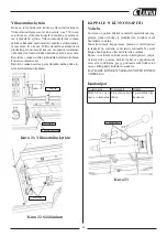
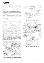
Clamp nut
Front offset Adj. screw
Rear offset
Adj. screw
Summary of Contents for 21149-0107
Page 1: ...Metal lathe ML1130 21149 0107...
Page 2: ......
Page 5: ...4...
Page 100: ...99 30 pav Past mos prispaud iamosios plok tel s var tai...
Page 132: ...131 Rys 30 ruby regulacyjne listew kli nowych sa wzd u nych...
Page 148: ...147 WIRING DIAGRAM 28 FRAM T BAK T START STOPP...
Page 149: ...148 EXPLOSION DIAGRAM...
Page 150: ...149...
Page 151: ...150...
Page 152: ...151...
Page 153: ...152...
Page 154: ...153...
Page 155: ...154...
Page 156: ...155...
Page 157: ...156...
Page 165: ......
Page 166: ......
Page 167: ......


