

57
If the carriage starts moving, immediately push the
STOP button and disengage the carriage feed lever,
then restart the lathe.
10. Allow the lathe to run for at least two full minutes
to make sure it is running satisfactorily and the chuck
is turning clockwise.
11. Press the “Stop”.
12. After the chuck has come to a complete stop, Press
the “Forward”.
13. Allow the lathe to run for at least two full minutes
to make sure it is running satisfactorily and the chuck
is turning counter clockwise.
14. Press the “Stop”.
15. After the lathe has come to a complete stop, en-
gage the carriage hand wheel, rotate the hand wheel to
center the carriage on the bed, then disengage the hand
wheel.
16. Engage the automatic carriage feed lever.
17. Turn the lathe ON.
18. Verify that the carriage moves along the bed, then
press the emergency stop button to turn the lathe OFF.
19. Disengage the feed lever.
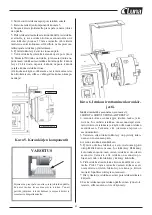
SECTION 4: OPERATE
General
The Model C8 will perform many types of operations
that are beyond the scope of this manual. Many of the-
se operations can be dangerous or deadly if performed
incorrectly.
The instructions in this section are written with the
understanding that the operator has the necessary
knowledge and skills to operate this machine. If at any
time you are experiencing difficulties performing any
operation, stop using the machine!
If you are an inexperienced operator, we strongly re-
commend that you read books, trade articles, or seek
training from an experienced lathe operator before
performing any unfamiliar operations. Above all, your
safety should come first!
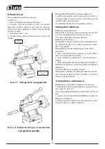
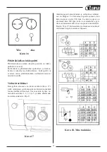
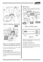
Controls
To get the most out of your machine, please take the
time to familiarize yourself with the various controls
and components shown in the Figures 3.
Note: The ”Milling/Drilling” option at the selector
switch is intended for the optional installation of a
milling attachment which is sold separately. Please
contact your authorized dealer for more information.
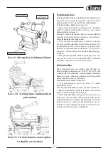
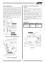
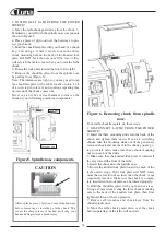
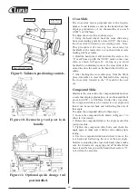
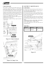
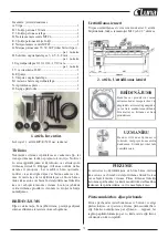
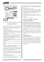
Figure 4. Compound Slide
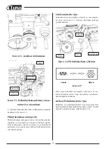
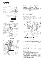
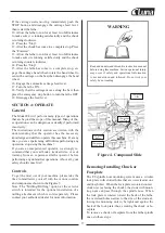
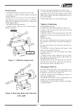
Removing/Installing Chuck or
Faceplate
The C8 spindle nose mounting system uses a circular
lock plate with slotted holes that are oversized at one
end (keyholes). When the lock plate is rotated counter-
clockwise (as facing the chuck), the studs with moun-
ting nuts can pass through the spindle nose. When
the lock plate is rotated toward the back of the lathe,
the oversized holes narrow to the size of the studs, al-
lowing the mounting nuts to be tightened against the
back of the lock plate, thus, securing the chuck or fa-
ceplate.
To remove a chuck or faceplate from the lathe spindle
nose, do these steps:
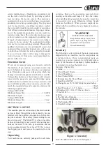
WARNING
Read and understand this entire instruction manual
before using this machine. Serious personal injury
may occur if safety and operational information
is not understood and followed. Do not risk your
safety by not reading
Compound
slide
Compound
cap screws
Compound
bolts
Compound
handwheel
Summary of Contents for 21149-0107
Page 1: ...Metal lathe ML1130 21149 0107...
Page 2: ......
Page 5: ...4...
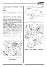
Page 100: ...99 30 pav Past mos prispaud iamosios plok tel s var tai...
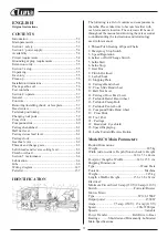
Page 132: ...131 Rys 30 ruby regulacyjne listew kli nowych sa wzd u nych...
Page 148: ...147 WIRING DIAGRAM 28 FRAM T BAK T START STOPP...
Page 149: ...148 EXPLOSION DIAGRAM...
Page 150: ...149...
Page 151: ...150...
Page 152: ...151...
Page 153: ...152...
Page 154: ...153...
Page 155: ...154...
Page 156: ...155...
Page 157: ...156...
Page 165: ......
Page 166: ......
Page 167: ......


