Lumber Jack DP13-580B Safety And Operating Manual Download Page 11


DP13-580B                                    09


Installation the chuck & arbor 

1. Locate the chuck in the box of parts. 
2. Tighten Philip’s head screws of the chuck 
guard to quill shaft. 
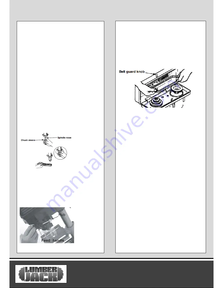
3. Clean out the tapered hole in the chuck, also 
clean the spindle nose with a clean cloth. Make 
sure there are no foreign particles sticking to the 
surfaces. The slightest piece of dirt on the 
spindle nose or the chuck will prevent the chuck 
from seating properly. This will cause the drill to 
“wobble” .  

NOTE: 

If the tapered hole in the chuck is 

extremely dirty, use a cleaning solvent on a clean 
cloth.  
4. Push the chuck up on the spindle nose as far 
as it will go.  
5. Turn the chuck sleeve clockwise and open the 
chuck jaws completely.  
6.  Lightly tap the nose of the chuck with a piece 
of wood to insure the proper seating of the 
chuck on the spindle.  


Installation the feed handles 

1. Locate the three feed handles among the 
loose parts.  
2. Screw the feed handle tightly into the 
threaded holes in the hub. 


Installing the belt guard knob 

1. To attach the belt guard knob, use the knob and 
a pan head screw from the loose parts bag. Insert 
the pan head screw into the belt guard and screw 
knob. Tighten. 

WARNING! : 

To


avoid possible injury, keep the 

guard in place and in proper working order while 
operating. 


Tensioning the belt 

NOTE: The drill press is shipped with the belt installed, 
but it should be properly tensioned before use. 

1. Lift the guard from the right side and keep it 
opened. 
2.


Release the belt tension lock handle located on 

the right side of the drill press head. Pull the right 
side of the motor towards the front to relieve the


spring tension of the belt. Tighten the belt tension 
lock handle. 
3. Choose the desired speed for your drilling 
operation, and move the belt to the indicated 
position. Refer to the chart on the inside of the 
belt guard. 
4. Loosen the belt tension lock handle and move 
the right side of the motor backwards to apply 
tension to the belt. 
5. Tighten the belt tension lock handle. 
NOTE: The belt should deflect approximately 1/2” 
by applying finger pressure at the mid-point of the 
belt between the pulleys. 
6. Close the belt guard. 
7. If the belt slips while drilling, readjust the belt 
tension. 


ASSEMBLY INSTRUCTIONS 

Summary of Contents for DP13-580B

Page 1: ...DP13 580B SAFETY AND OPERATING MANUAL 13mm Bench Top Drill Press DP13 580B ORIGINAL INSTRUCTIONS...

Page 2: ...th all information necessary for using the product safely and to ensure its long service life Closely observe all safety information in these instructions General Power Tool Safety Warnings Symbols Ca...

Page 3: ...the cord Never use the cord for carrying pulling or unplugging the power tool Keep cord away from heat oil sharp edges or moving parts Damaged or entangled cords increase the risk of electric shock e...

Page 4: ...the power tool or these instructions to operate the power tool Power tools are dangerous in the hands of untrained users e Maintain power tools Check for misalignment or binding of moving parts break...

Page 5: ...afety Warning for Bench Drills 8 1 Always wear hairnet for long hair and make sure you are wearing safety goggles 8 2 Do not wear gloves ties or loose clothing 8 3 while drilling make sure the piece i...

Page 6: ...ays require a three wire extension cable 10 3 As the distance from the supply outlet increases you must use a heavier gauge extension cable Using extension cables with inadequately sized wire causes a...

Page 7: ...es Caution Wear ear defenders The impact of noise can cause damage to hearing Amperes 7 5M 15M 25M 30M 45M 60M 0 2 0 6 6 6 6 6 6 2 1 3 4 6 6 6 6 6 6 3 5 5 0 6 6 6 6 10 15 5 1 7 1 10 10 10 10 15 15 7 1...

Page 8: ...ity 13mm Max Distance from Chuck to the table 180mm Max Distance from Chuck to the base 255mm Table Size 165X165mm Base Size 280X180mm Over all Height 580mm Dimensions L x M x H 580 x 404 x 186mm Nett...

Page 9: ...e 13 Table Bevel Lock 14 Table 15 Feed Handle 16 Chuck 17 Feed Stop Rod 18 Stop Nuts 19 On Off Switch 20 Chuck Guard Unpacking Instructions 1 Separate all parts from packaging materials and check all...

Page 10: ...tre Base and column assembly 1 Position the base on the floor Remove the protective covering and discard 2 Remove protective sleeve from the column and discard Place the column assembly on the base al...

Page 11: ...he belt guard knob use the knob and a pan head screw from the loose parts bag Insert the pan head screw into the belt guard and screw knob Tighten WARNING To avoid possible injury keep the guard in pl...

Page 12: ...1 long When using a small drill bit do not insert it so far that the jaws touch the flutes spiral grooves of the bit Make sure the drill bit is centred in the chuck before tightening the chuck with t...

Page 13: ...there is not enough tension on the spring repeat steps 4 8 moving one notch each time and checking the tension after each repetition 10 Proper tension is achieved when the quill returns gently to the...

Page 14: ...he work piece to prevent splintering Switching on Lift the safety stop case and engage the green start button Simply press the Red button to stop the machine Switching on Lift the safety stop case and...

Page 15: ...ll bit Wood splinters on underside 1 No back up material under work piece 1 Use back up material Work piece moving 1 Not supported or clamped properly 1 Clamp the work piece Drill Bits Binding to work...

Page 16: ...ected to wear at different rates depending on usage 1 2 7 The product has not been used for hire purposes 1 2 8 The product has been purchased by you as the guarantee is not transferable from a privat...

Page 17: ...product for any commercial business or resale purposes and we have no liability to you for any loss of profit loss of business business interruption or loss of business opportunity 3 2 This Guarantee...

Page 18: ...rill Press DP13 580B Is in compliance with the regulations included in the Directives 2006 95 EC EC DECLARATION OF CONFORMITY Certificate for EC type examination delivered by Ente Certificazione Macch...

Page 19: ...etaining ring shaft 128 Rod 108 Ball bearing 129 Pinion shaft 109 Spacer 130 Hex nut 110 Pulley insert 131 Special set screw 111 Spindle pulley 132 Spring washer 112 Pulley nut 133 Pan hd screw 113 Co...

Page 20: ...Pointer 160 Stop rod 148 Power cord 161 Table support 149 Quill gasket 162 Lock handle 150 Ball bearing 163 Column 151 Quill 164 Base 152 Pan hd screw 165 Hex bolt 153 Stop collar 166 Hex bolt 154 Ret...

Page 21: ...DP13 580B 19 Parts Diagram...

Page 22: ...DP13 580B 20 Parts Diagram...

Reviews: