


363-206-295
Circuit Pack Descriptions
Issue 1
December 1997
7-23
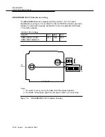
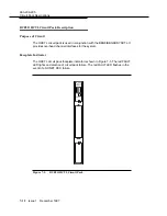
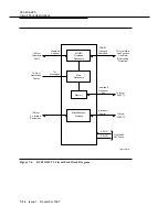
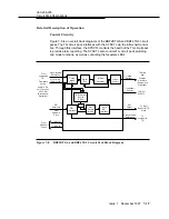
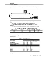
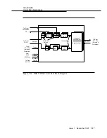
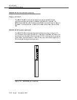
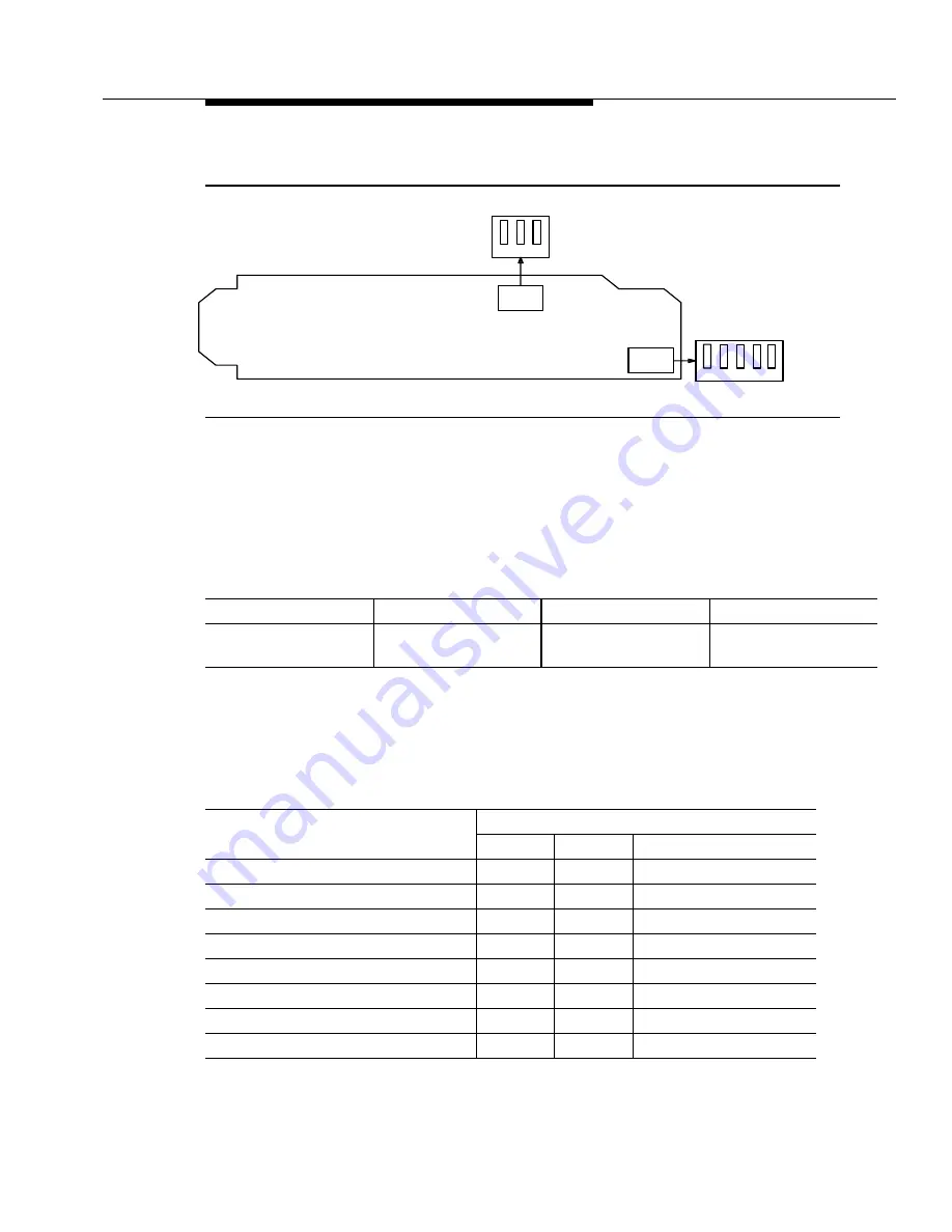
Figure 7-9 shows the location of the option switches for the BBF2B TGS circuit pack.
Figure 7-9.
TG Option Switches for DDM-2000 OC-3 (Sheet 1 of 2)
Notes
:
1. The switches are set by moving the slide toward the desired position.
2. If the invalid switch setting is selected, the FAULT LED lights and an alarm is
generated.
3. The main OLIU is the default reference when in Line Timing or SYNC OUT mode.
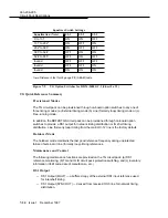
Note
: Controls line coding and frame format for both DS1 input and output.
* Factory default.
* Factory default.
TG DS1 Line Coding and Frame Format Switch Settings (Note)
DS1 Line Code
Switch S1-1
DS1 Frame Format
Switch S1-2
AMI *
B8ZS
ON
OFF
SF *
ESF
ON
OFF
TG Timing Mode Switch Settings
Timing Mode
Switch Settings
S1-3
S1-4
S1-5 (DS1 Output)
Free-Running
ON
ON
OFF
DS1 External, MULT Mode*
OFF
ON
OFF
Line Timing Main
OFF
OFF
OFF
Line Timing, SYNC OUT Mode
OFF
OFF
ON
DS1 External, SYNC OUT Mode
OFF
ON
ON
Invalid
ON
OFF
ON
Invalid
ON
OFF
OFF
Invalid
ON
ON
ON
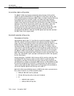
Connector
Edge
S2
OFF
ON
3
2
1
5
S1
OFF
ON
Component Side
4
3
2
1


