background image

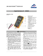
METRA HIT

16I/L/T

Analog Digital Multimeter 
with Insulation Measurement

3-348-892-02

9/5.06

Operating Instructions

Summary of Contents for METRA HIT 16I/L

Page 1: ...METRA HIT 16I L T Analog Digital Multimeter with Insulation Measurement 3 348 892 02 9 5 06 Operating Instructions ...

Page 2: ...2 GMC I Gossen Metrawatt GmbH 18 9 10 11 12 13 20 19 14 15 17 16 1 7a 5 5a 5 5b 3 3a METRA HIT 16I L METRA HIT 16T 2 2 3 4 4a 6 7 max 600 V max 600 V 8 8 ...

Page 3: ...ong as key is held chapter 14 5b Key for activating and deactivating chapter 15 of insulation resistance measurement 6 Rotary switch for measuring functions chapter 7 ff 7 Connector jacks for multimeter measurement chapter 3 7a Connector jacks for insulation resistance measurement chapter 14 chapter 15 8 DKD calibration mark chapter 1 LCD Key 9 Symbol for indication of continuous operation 10 Digi...

Page 4: ...ment with the WZ12B Clip On Current Transformer 13 10 Diode and Continuity Testing 14 11 Capacitance Measurement 15 12 Frequency Measurement 15 13 Temperature Measurement 16 14 Insulation Resistance Measurement with the METRA HIT 16I L 17 14 1 Preparation for Measurement 17 14 2 Insulation Resistance Measurement 18 14 3 Conclusion of Measurement and Discharging 18 14 4 Evaluation of Measurement Va...

Page 5: ...ltimeter described herein is a portable instrument which can be held in one hand during measurements Only such measurements are performed as described in chap ters 7 to 15 The measuring instrument including measuring cables and plug on test probes is only used within the measuring category indi cated under the heading Electrical Safety on page 26 refer to the table on page 6 for the meaning of the...

Page 6: ...s doubled or reinforced insulation VDE testing authority approval mark CSA approval mark North American test authority Indicates EC conformity This device may not be disposed of with the trash Further information regarding the WEEE mark can be accessed on the Internet at www gossenmetrawatt com by entering the search term WEEE DKD calibration mark red seal CAT Definition I Measurements in electric...

Page 7: ...ress the ON OFF key Activation is acknowledged with an acoustic signal As long as the key remains pressed all segments of the liquid crystal display LCD are active The LCD is shown on page 2 After the key is released the instrument is ready for operation After the instrument has been switched off it cannot be switched back on for at least 3 seconds Note Electrical discharge and high frequency inte...

Page 8: ...hen the instrument is switched back to automatic range selection in the 30 mV or 300 mV ranges the 3 V range is activated 1 METRA HIT 16I L only 3 3 Quick Measurements If you wish to perform quicker measurements than those possible with the automatic measuring range selection function make sure to establish the appropriate measuring range by manual measuring range selection i e by selecting the me...

Page 9: ... especially useful when contacting the mea suring point with the test probes requires your full attention After the measurement value has been acquired and the appropriate condition has been fulfilled according to the following table the measured quantity is frozen at the digital display and an acoustic signal sounds The test probes can now be removed from the mea suring point and the measurement ...

Page 10: ...accomplished manually However this causes the deletion of currently stored minimum and maximum values The MIN MAX function is deactivated by pressing and holding key DATA MIN MAX approx 1 s by turning the rotary switch or by switching the instrument off and back on again Function MIN MAX DATA MIN MAX 3 Meas Range MIN and MAX Measurement Val ues Reaction at Instrument Display Acous tic Signal Value...

Page 11: ... 00 1 digit appears at the LCD with a blinking deci mal point The voltage which was displayed at the moment the key was activated serves as a reference value max 200 digits It is automatically subtracted from subsequently measured values Zero balancing can be deleted by pressing and holding the multifunction key FUNC after which deletion is acknowledged with a twice repeated acoustic signal by swi...

Page 12: ...a watt GmbH The bonding terminal must be grounded for measure ments of this type and all required safety precautions must be observed 7 5 Duty Cycle Measurement only with METRA HIT 16L With a duty cycle measurement you can determine the ratio of pulse duration to cycle time of regularly recurring square wave sig nals Set the function selector switch to V Hz or V Hz Connections are made in the same...

Page 13: ...cally subtracted from subse quently measured values Zero balancing can be deleted by pressing and holding the multifunction key FUNC after which deletion is acknowledged with a twice repeated acoustic signal by switching the instrument off See chapter 14 and chapter 15 for insulation resistance measure ment 9 Alternating Current Measurement with the WZ12B Clip On Current Transformer The rotary sel...

Page 14: ...gnal If the acoustic signal function is activated the instrument gener ates a continuous tone for displayed values between 0 and approx 1 1 V or for 1 8 kΩ Acoustic Signal ON default condition After the diode and continuity testing function has been activated with the rotary switch the acoustic signal is always activated The symbol 19 is simultaneously displayed at the LCD Repeated brief activatio...

Page 15: ...racted from subsequently measured values Zero balancing can be deleted by pressing and holding the multifunction key FUNC after which deletion is acknowledged with a twice repeated acoustic signal by switching the instrument off 12 Frequency Measurement Frequency measurement is possible in all voltage measuring ranges in the AC and DC operating modes Set the rotary switch to V or V Apply the measu...

Page 16: ...NC repeatedly until the current cable resistance value is displayed The resistance value is then displayed at the LCD which will be used for automatic compensation after the temperature measur ing range has been activated Correction resistance can be adjusted as follows Press the DATA MIN MAX key to increase the value or the AUTO MAN key to reduce the value The value is changed by one digit each t...

Page 17: ...abled The interference voltage is displayed at the LCD If a voltage of greater than 1000 V has been applied this is indicated additionally with an acoustic signal High Voltage Do not touch the conductive ends of the test probes after insulation resistance measurement has been acti vated at the instrument A current with a value of 2 5 mA limited by the instru ment may flow over your body and althou...

Page 18: ...s the AUTO MAN key until acknowledgement is indi cated with an acoustic signal Deactivation Briefly press the multifunction key FUNC 14 3 Conclusion of Measurement and Discharging After the measurement has been completed any residual voltage is displayed which may be caused by conductor capacitance Discharge the DUT by turning the selector switch to the V1MΩ position Contact with the DUT must be m...

Page 19: ...e endangering in such cases Turn the selector switch to MΩISO_a b then to MΩISO_j a and finally to MΩISO_b j in order to display possible interference volt age for all three possible conductor pair combinations Note Insulation resistance may only be measured at voltage free objects If an interference voltage of 50 V is present within the system insulation resistance measurement is disabled The int...

Page 20: ...e required limit values are not violated 16 RS232C Interface The multimeters are equipped with an serial infrared interface for the transmission of measurement data to computer systems The measurement values are optically transmitted through the housing to an interface adapter via infrared light which can be plugged onto the multimeter Data are then transmitted to the computer by means of a RS232 ...

Page 21: ...10 MΩ 40 pF A 2 30 100 A 10 100mA open circuit voltage Ω 30 00 Ω 10 mΩ max 3 2 V 300 0 Ω 100 mΩ max 3 2 V 3 000 kΩ 1 Ω max 1 25 V 30 00 kΩ 10 Ω max 1 25 V 300 0 kΩ 100 Ω max 1 25 V 3 000 MΩ 1 kΩ max 1 25 V 30 00 MΩ 10 kΩ max 1 25 V 2 000 V 1 mV max 3 2 V Meas Function Measuring Range Resolution Discharge Resis tance U0 max F 30 00 nF3 10 pF 250 kΩ 2 5 V 300 0 nF 100 pF 250 kΩ 2 5 V 3 000 μF 1 nF 2...

Page 22: ...s 30 00 V 300 0 V 600 V A 100 A 2 5 3 10 digits 120 A cont Ω 30 00 Ω 0 5 3 2 600 V DC AC rms sine max 10 s 300 0 Ω 0 5 3 3 000 kΩ 0 4 1 30 00 kΩ 0 4 1 300 0 kΩ 0 4 1 3 000 MΩ 0 6 1 30 00 MΩ 2 0 1 2 000 V 0 25 1 Meas Function Measuring Range Digital Display Intrinsic Error of rdg digit at reference conditions Overload Capacity1 Value Duration F 30 00 nF 1 0 3 3 600 V DC AC rms sine max 10 s 300 0 n...

Page 23: ...10 0 kΩ 0 1 kΩ 3 of rdg 10 d 0 280 3 100 MΩ 02 80 31 00 MΩ 028 0 310 0 MΩ 1 kΩ 10 kΩ 100 kΩ 3 of rdg 2 d Meas Func tion Switch Setting Nominal Voltage UN Open Circuit Voltage Uo Nominal Current IN Short Circuit Current Ik 16I L V1MΩ MΩISO 1000V 500 V 1 15 x UN 1 0 mA 2 5 mA 1000 V 1 15 x UN 1 0 mA 2 5 mA 16T MΩISO 100V 100 V 1 15 x UN 1 0 mA 1 5 mA Meas Func tion Switch Setting Nominal Voltage UN ...

Page 24: ...ror 1 of rdg digit Tempera ture 0 C 21 C and 25 C 40 C 30 300 mV 1 0 3 3 300 V 0 15 1 600 V 0 2 1 V 0 4 2 30 Ω 2 0 15 2 300 Ω 0 25 2 3 kΩ 3 MΩ 0 15 1 30 MΩ 1 0 1 30 nF2 3 μF 0 5 2 5 30 μF 2 0 2 Hz 0 5 1 5 Digit 200 200 C 0 5 K 2 200 800 C 0 5 2 300 400 F 1 0 K 4 400 999 F 0 5 2 16I MΩISO 0 25 2 16T MΩ 0 25 2 Measured Quantity Frequency 15 Hz 30 Hz 3 600 V 1 0 3 30 Hz 45 Hz 0 5 3 65 Hz 400 Hz 2 0 3...

Page 25: ...rror DATA 1 digit MIN MAX V 2 digits Influencing Quantity Sphere of Influence Measuring Range Damping Common Mode Interference Voltage interference max 600 V V 120 dB interference max 600 V 50 Hz 60 Hz sine 3 V 30 V 80 dB 300 V 70 dB 600 V 1 60 dB Series Mode Interference Voltage interference V respective nom value of meas range max 600 V 50 Hz 60 Hz sine V 50 dB interference max 600 V V 110 dB Me...

Page 26: ...cond Power Supply Battery 9 V flat cell battery alkali manganese cell per IEC 6 LR 61 1 Times 0 7 with active interface 2 Battery test automatic display of symbol when battery voltage falls below approx 7 V Electrical Safety Protection Class II per EN 61010 1 2001 VDE 0411 1 2002 Measuring Category II III Nominal Voltage 600 V 300 V Pollution Degree 2 2 Test Voltage 3 5 kV per EN 61010 1 2001 VDE ...

Page 27: ...ould be replaced as soon as possible You can continue to take measure ments but the accuracy of the instrument may be negatively influ enced The instrument is powered by a 9 V flat cell battery in accordance with IEC 6 LR 61 Use only alkali manganese cells which comply with IEC 6 LR61 Replacing the Battery Lay the instrument onto its face loosen the two screws at the rear panel and lift out the ho...

Page 28: ...with the trash Please contact our service department regarding the return of old devices see chapter 20 19 Accessories 19 1 General The wide range of accessories available for our multimeters is regu larly checked for compliance with the currently valid safety stan dards and is extended to include new ranges of application if required If you are looking for the appropriate up to date accesso ries ...

Page 29: ...ternating current values AC active power AC apparent power DC power capacitance and frequency DKD Calibration Certificate Reprints If you need to order a reprint of the DKD calibration certificate for your instrument please include the ID number shown in the upper most and lowermost fields of the calibration certificate We do not need the instrument s serial number 21 Warranty The warranty period ...

Page 30: ...nge without notice A pdf version is available on the internet GMC I Gossen Metrawatt GmbH Thomas Mann Str 16 20 90471 Nürnberg Germany Phone 49 0 911 8602 0 Fax 49 0 911 8602 669 E Mail info gossenmetrawatt com www gossenmetrawatt com ...

Reviews: