


VERIFICHE
/
COOLER CAPACITY CHECKS
/
CONTROLES
/
LEISTUNGSUBERPRUFUNG /
KONTROLA PRACY CH
Ł
ODNICY
BHD... SHDN
ITALIANO
-
BMD... SMD...
POLSKI
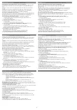
Rilevare le seguenti temperature e pressioni: (Fig. 5)
- Temperatura di cella nella zona aria ingresso all’evaporatore.
- Temperatura di evaporazione, corrispondente alla pressione refrigerante all’uscita dell’e-
vaporatore.
Trs - Temperatura di surriscaldamento del refrigerante, sulla linea di aspirazione in prossimità
del bulbo della valvola termostatica.
N.B. - Per un uso ottimizzato dell’evaporatore il surriscaldamento (Trs-Te) non dovrà su-
perare 0,7 x (Ts’-Te).
Accertato che la valvola termostatica sia adeguata alle condizioni di impianto, compatibilmente
alle pendolazioni del sistema, mantenere il più basso surriscaldamento possibile al fine di otte-
nere dall’aeroevaporatore la massima potenza.
Ts’
Te
Nale
ż
y dokona
ć
nast
ę
puj
ą
cych pomiarów temperatury i ci
ś
nienia (rysunek 5) :
Ts’ – Temperatura powietrza w komorze po stronie wej
ś
ciowej do parownika
Te – Temperatura parowania, odpowiadaj
ą
ca ci
ś
nieniu czynnika ch
ł
odniczego na wyj
ś
ciu z parownika.
Trs – Temperatura przegrzania czynnika ch
ł
odniczego, na linii ssawnej w pobli
ż
u czujnika zaworu
termostatycznego.
Uwaga: Dla optymalnej pracy parownika, przegrzanie (Trs-Te) nie powinno przekracza
ć
0,7 x (Ts’-Te).
Po upewnieniu si
ę
,
ż
e zawór termostatyczny jest prawid
ł
owo zainstalowany i dostosowany do warunków
pracy danego systemu, nale
ż
y utrzyma
ć
jak najni
ż
sze przegrzanie, aby zapewni
ć
maksymaln
ą
wydajno
ść
parownika
ENGLISH
Take the following temperature and pressures: (Fig. 5)
- Cold room air inlet temperature to the unit.
- Evaporating temperature, relating to the refrigerant pressure on the unit cooler outlet.
- Refrigerant superheat temperature, on suction line near thermostatic valve bulb.
- For optimum unit cooler performance the superheat (Trs-Te) should not be higher
than 0,7 x (Ts’-Te).
The thermostatic valve fitted must be correctly sized for the installation conditions and adjusted
for correct system operation.
N.B. Keep the superheat as low as possible to obtain maximum unit cooler performance.
Ts’
Te
Trs
N.B.
FRANCAISE
Relever les températures et pressions suivantes: (Fig.5)
- Témperature de la chambre froide dans la zone d’entrée d’air de l’évaporateur.
- Témperature d’évaporation, correspondante à la pression du réfrigérant à la sortie de l’é-
vaporateur.
Trs - Témperature de surchauffe du réfrigérant, sur la ligne d’aspiration à proximité du bulbe
de la vanne thermostatique.
N.B. - Pour utiliser l’aéroévaporateur dans les conditions optimales, la surchauffe (Trs-Te)
ne doit pas être supérieure à 0,7 x (Ts’-Te).
Si l’on s’assure que la vanne thermostatique est conforme aux conditions d’installation établies
et compatible avec les conditions de fonctionnement du système, le rendement de l’évapora-
teur sera d’autant plus grand que la surchauffe sera plus faible.
Ts’
Te
Rys. 5
DEUTSCH
Folgende Temperaturen und Drücke sind zu messen: (Fig. 5)
- Kühlraumtemperatur an der Lufteintrittsseite des Verdampfers.
- Verdampfungstemperatur über Druck am Verdampferende.
- Fühlertemperatur an der Saugleitung nahe beim Fühler des Expansionventils.
- Für eine optimale Verdampferarbeitsweise darf die Überhitzung (Trs-Te) nicht höher
sein als 0,7 x (Ts’-Te).
Das Expansionventil muß entsprechend der installerten Leistung und Betriebsbedingungen ausge-
wählt werden.
N.B. Die Uberhitzung soll möglichst klein gehalten werden, um die maximale Verdampferleistung zu
erreichen.
Ts’
Te
Trs
N.B.
Pe
Ts
1
Trs
/
Modell
/
Te
/
ROZMRA
Ż
ANIE ELEKTRYCZNE
SBRINAMENTO ELETTRICO
/
ELECTRIC DEFROST
/
DEGIVRAGE ELECTRIQUE / ELEKTRISCHE ABTAUUNG
Modello
/
Type
/
Modèle
Model
338 – 32
222 – 50
144 - 80
294 – 32
196 – 50
124 - 80
2
DE10
230
2380
4760
BHDN...E - SHDN...E
BMDN...E - SMDN...E
BHDS...E - SHDS...E
BMDS...E - SMDS...E
Resistenze elettriche
Eletric heaters
Résistances electriques
Helzstäbe
Grza
ł
ki elektryczne
57 – 32
37 – 50
25 - 80
52 – 32
34 – 50
21 - 80
85 – 32
56 – 50
36 - 80
74 – 32
49 – 50
31 - 80
2
DE6
230
650
1300
126 – 32
82 – 50
53 - 80
114 – 32
73 – 50
46 - 80
2
DE7
230
1000
2000
169 – 32
111 – 50
72 - 80
146 – 32
98 – 50
62 - 80
2
DE8
230
1200
2400
/
253 – 32
166 – 50
108 - 80
221 – 32
148 – 50
93 - 80
2
DE9
230
1770
3540
423 – 32
278 – 50
180 - 80
368 – 32
245 – 50
155 - 80
2
DE11
230
2900
5800
N°
Mod./ Typ
2
DE6
230
650
1300
V
W (x1)
Razem W
Collegamenti elettrici / Electric connections / Connexions électriques / Anschlüsse
Po
łą
czenia elektryczne
A
A
A
A
B
B
B
A
B
B
B
DE
DE
L
N
PE
N
R
S
T
PE
N
R
S
T
PE
1 - 230 V 50-60 Hz
1 - 230 V 50-60 Hz
Resistenze elettriche
Electric heaters
Résistance électriques
Heizstäbe
Grza
ł
ki elektryczne
3 ~ 400 V 50-60 Hz
STANDARD
R
S
T
6
3 ~ 230 V 50-60 Hz


