AHE00049 2002
6
Alfa LU-VE is a trademark registered and owned by LU-VE Group.
Alfa LU-VE reserves the right to change specifications without prior notification.
3.2 Lifting
Condensers and gas coolers can be lifted from above using a hoist. Ensure that the weight is
distributed evenly over all the lifting lugs. In the case of long heat exchangers, the use of a hoisting
beam may be required. Use of a fork-lift is permitted with proper characteristics in relation to weight
and depth of the heat exchanger. Weight information and dimensions are shown on the product
label and/or in the relevant product documentation. It is important that weight is distributed evenly.
Direct or indirect lifting under the coil block is not permitted. All lifting procedures must be carried
out carefully by properly qualified personnel, ensuring absolute safety at all times.
If in doubt about the proper hoisting or lifting method, please check with Alfa LU-VE. Check the
instruction manual for detailed lifting instructions about specific heat exchanger models.
3.3 Mounting
All heat exchangers must be set up level. Weight information and dimensions are listed on the
product label and/or in the relevant product documentation.
3.4 Pipework and connections
All pipework and connections must be made in
accordance with good refrigeration design and
installation practice. Do not bend the con-
nection tubes! Ensure that no stresses are trans-
mitted to the pipework. All pipework should be
adequately supported to prevent vibration or
external load on the unit headers, etc.
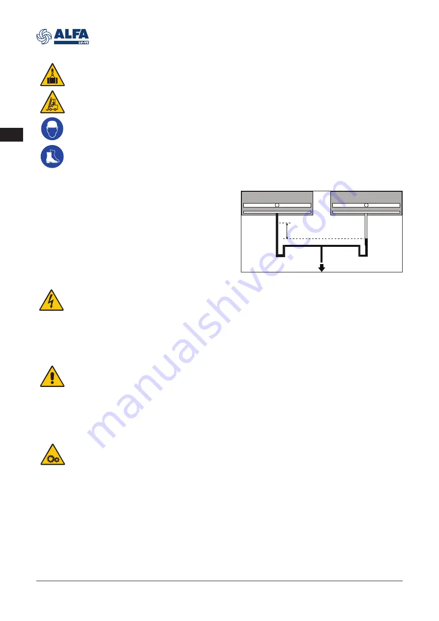
If condensers are connected in parallel,
allowance must be made for the fall in pressure
on the refrigerant side. If necessary, fall lines
must be applied.
3.5 Electrical connections
All electrical connections must be made in accordance with the locally valid regulations and in con-
formance with good installation practice. The site supply voltage, frequency, accepted power rating
and number of phases must comply with the details on the technical documentation. All electrical
supply lines must be connected to the terminal boxes through suitable waterproof glands using bot-
tom entry or, in case of horizontal installation, the cable is routed to form a water trap.
If the heat exchangers are installed outdoors and there is to be an appreciable delay in putting the
plant into operation, a temporary electrical supply should be connected to each motor, sufficient
to run for at least 4 hours. This procedure should be carried out at least once every 4 weeks, until
the heat exchanger is fully operational. It is up to the end user to verify the conditions for protec-
tion by automatic disconnection of supply, according to applicable standards. Heat exchangers are
designed for TN power systems. The insulation fault protection must be part of power supply of the
heat exchanger and it is not supplied by the manufacturer.
3.6 Power failure
In order to avoid damage to the compressor, the refrigerant supply must be closed in the event of
power failure, e.g. by closing the magnetic valve. Safety measures elsewhere in the system will
prevent the pressure in the heat exchanger from exceeding the design pressure PS.
3.7 Fan motors
The maximum load of the motors and the recommended settings for the overload relays are to be
respected. The built-in thermal overload protection must be integrated in the control circuit when
a connection in the terminal box is present. The electrical control circuit should be arranged with
a manual reset device in order to prevent continuous on/off switching (tripping) of the motors.
Suppliers and manufacturers of electrical motors provide no guarantee for motors that are com-
busted through overload. For correct installation and operation of fan speed control systems, follow
instructions given in the controller and fan manuals.
3.8 Sound level
Sound levels are specified according to EN13487. Depending on construction and the materials
used for the space in which the heat exchangers are placed, the measured sound level values may
vary significantly from the documented value.
EN
P
1
– P
2
syphon
syphon


